Hydraulic distributor of hydraulic suspension device

A hydraulic distributor and hydraulic suspension technology, which is applied in the direction of fluid pressure actuators, valve devices, adjustment devices, etc., can solve problems such as vacuum formation, complex structure, and cavitation

Pending Publication Date: 2020-11-20
WEIFANG LICHUANG ELECTRONICS TECH
View PDF4 Cites 4 Cited by
  • Summary
  • Abstract
  • Description
  • Claims
  • Application Information

AI Technical Summary

Problems solved by technology

[0005] 1) When the agricultural equipment is in the farming state, frequent use of the pressure of the main oil circuit will cause waste of system energy;
[0006] 2) Using four solenoid valves to control the movement of the spool, the structure is complex
[0015] During transition operations, due to the difference in effective cross-sectional area between the rod chamber and the rodless chamber of the lifting cylinder, when the cylinder body of the lifting cylinder moves upwards instantaneously relative to the piston rod, the volume of hydraulic oil flowing out of the rodless chamber is more than The volume of hydraulic oil required by the rod cavity affects the shock absorption effect; similarly, when the cylinder body of the lift cylinder moves down instantly relative to the piston rod of the lift cylinder, the volume of hydraulic oil flowing out of the rod cavity is less than that without The volume of hydraulic oil required by the rod chamber, the rodless chamber will form a vacuum, causing cavitation

Method used


Image

  • Hydraulic distributor of hydraulic suspension device
  • Hydraulic distributor of hydraulic suspension device
  • Hydraulic distributor of hydraulic suspension device

Examples


Embodiment Construction

[0043] The present invention will be further described below in conjunction with the accompanying drawings and embodiments.

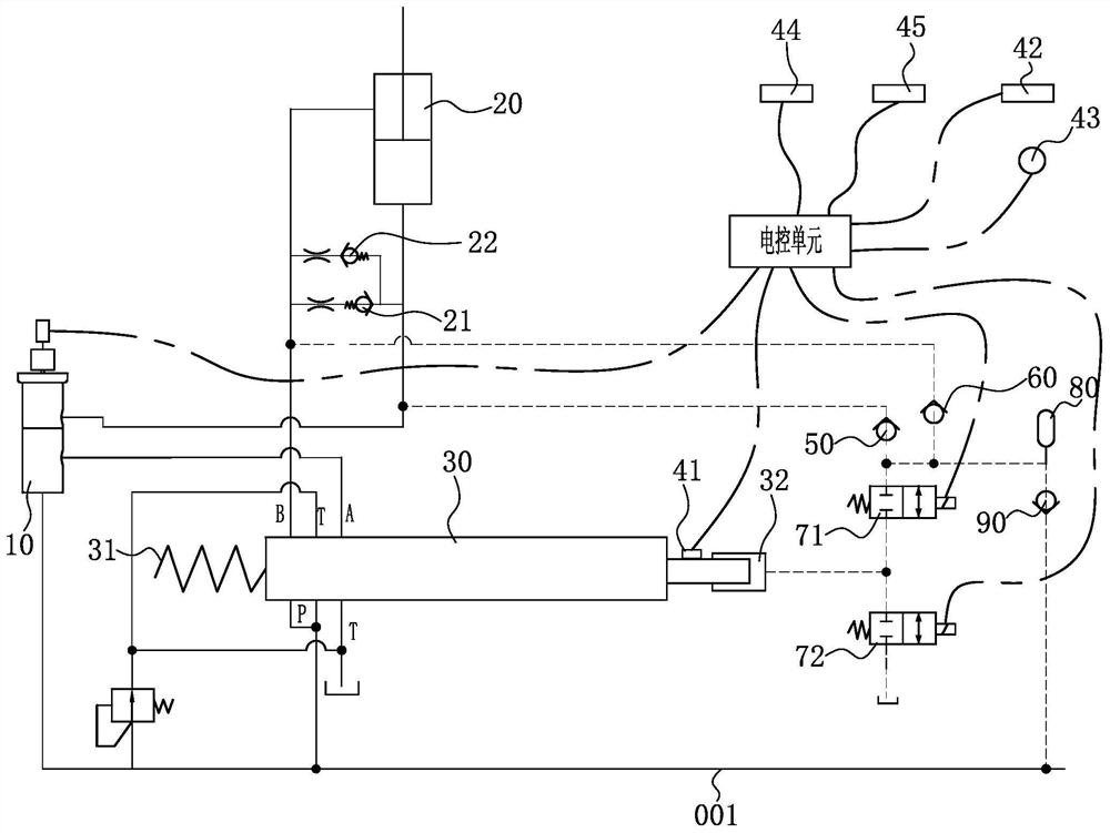
[0044] Such as figure 1 As shown, an intelligent control system of a hydraulic suspension device can intelligently control the hydraulic suspension device of a tractor, and can also intelligently control the hydraulic suspension device of other agricultural equipment.

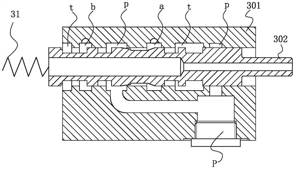
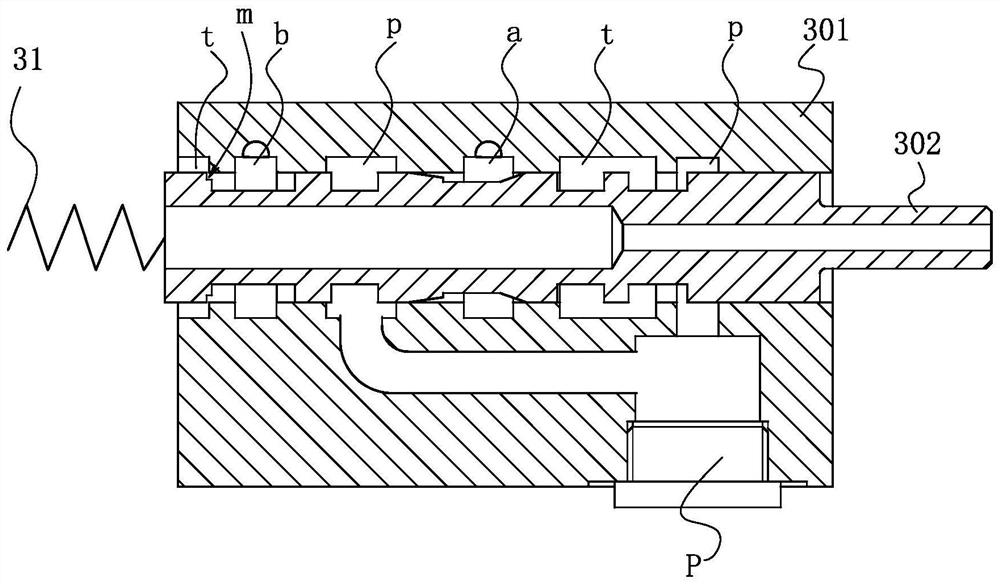
[0045] refer to figure 2 , the hydraulic distributor 30 includes a valve body 301 and a valve stem 302 arranged in the valve body 301, the valve body 301 is provided with a first working oil chamber a communicating with the first working oil port A, and a second working oil chamber a communicated with the second working oil port A. The second working oil chamber b communicated with the oil port B, the pressure oil chamber p communicated with the pressure oil port P and the oil return chamber t communicated with the oil return port T.

[0046] Such as figure 1 As shown, the first work...


PUM


Abstract

The invention discloses a hydraulic distributor of a hydraulic suspension device. The hydraulic distributor is characterized in that two adjacent valve rod sections of a valve rod are correspondinglyprovided with an ascending speed control conical surface and a descending speed control conical surface, and when the hydraulic distributor is in an ascending working position, a pressure oil cavity and an oil return cavity of the hydraulic distributor are disconnected; and the valve rod and a valve body form an ascending speed throttling gap at the ascending speed control conical surface, a firstworking oil cavity is in communication with the pressure oil cavity through the ascending speed throttling gap, the second working oil cavity is in communication with the oil return cavity, and the axial displacement of the valve rod is controlled through an electric control unit, so that the throttling area of the ascending speed throttling gap can be changed, the ascending speed of a farm implement can be controlled, and similarly, the descending speed of the farm implement can also be controlled.

Description

technical field [0001] The invention relates to the technical field of hydraulic suspension devices for agricultural equipment, in particular to a hydraulic distributor for hydraulic suspension devices. Background technique [0002] The hydraulic suspension device of agricultural equipment (such as tractors) is used to connect suspended or semi-suspended agricultural implements, perform agricultural implement lifting and plowing depth adjustment, and realize loading and hydraulic power output, etc. The hydraulic suspension device consists of a hydraulic system and a suspension mechanism. The hydraulic system includes an oil pump, a distributor, a lifting cylinder, and an oil cylinder control mechanism. The suspension mechanism includes an upper pull rod, a lower rod, and a lifting arm. On the one hand, by manipulating the distributor, the raising, lowering, neutralization and floating of the agricultural implements can be realized, so that the tractor has the functions of po...

Claims


Application Information

Patent Timeline
Patent Type & Authority Applications(China)
IPC IPC(8): F15B13/044F15B11/042F15B11/08F16K1/38F16K3/314F16K27/00A01B63/10
CPCA01B63/1006F15B11/042F15B13/0405F15B13/044F16K1/38F16K3/314F16K27/00
Inventor 王立峰王秀强李武海李克旭王孟晓吴龙龙尹伟科王昊天
Owner WEIFANG LICHUANG ELECTRONICS TECH
Why Eureka
Try Eureka