Glazing device for artware ceramic
A technology for handicrafts and ceramics, applied in the field of glazing devices for handicrafts, to achieve the effects of simple operation, reduced labor intensity, and prevention of waste
- Summary
- Abstract
- Description
- Claims
- Application Information
AI Technical Summary
Problems solved by technology
Method used
Image
Examples
Embodiment 1
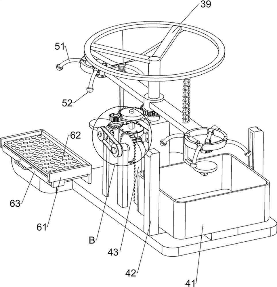
[0023] A glazing device for handicraft ceramics, such as Figure 1-5 As shown, it includes a bottom plate 1, a mounting column 2, a material loading and unloading moving mechanism 3, and a glazing mechanism 4. The top of the bottom plate 1 is connected with a mounting column 2, and the material loading and unloading moving mechanism 3 is installed on the mounting column 2. The top of the bottom plate 1 is installed with an upper The glaze mechanism 4, the glaze mechanism 4 and the material loading and unloading moving mechanism 3 are connected by transmission.
[0024] The material handling and moving mechanism 3 includes a fixed column 31, a sliding connecting plate 32, a first gear 33, a half-toothed gear 34, a servo motor 35, a fixed frame 36, a bracket 37, a return spring 38, a ring frame 39 and a top block 310 , the top of the mounting column 2 is connected with a fixed column 31, the outer wall of the fixed column 31 is rotatably connected with a sliding connecting plate...
Embodiment 2
[0028] On the basis of Example 1, such as figure 1 , image 3 with Image 6As shown, a clamping mechanism 5 is also included, and the clamping mechanism 5 includes an arc rod 51, a clamp block 52, a first sliding sleeve 53, a first rotating shaft 54, a second sliding sleeve 55, a slotted connecting rod 56, a first The two rotating shafts 57 and the contact plate 58, the left and right ends of the sliding connecting plate 32 are connected with the first rotating shaft 54, and the first rotating shaft 54 is connected with four first sliding sleeves 53 evenly spaced in the circumferential direction. The cover 53 is connected with an arc rod 51, the outer end of the arc rod 51 is connected with a clip 52, the inner end of the arc rod 51 is connected with a second sliding sleeve 55, and the second sliding sleeve 55 is connected with two openings in a symmetrical sliding manner. Slotted connecting rods 56 , a second rotating shaft 57 is connected between the two slotted connecti...
Embodiment 3
[0031] On the basis of Example 2, such as figure 1 with image 3 As shown, it also includes a surplus material recovery structure 6, and the surplus material recovery structure 6 includes a second guide rail frame 61, a bushing plate 62 and a movable material receiving box 63, and the left side of the front side of the bottom plate 1 is connected with a second rail frame 61, the second rail frame 61 is The upper part in the second rail frame 61 is connected with a leaking plate 62 , and the second rail frame 61 on the lower side of the leaking plate 62 is slidably connected with a movable material receiving box 63 .
[0032] The glazed pottery can be removed and placed on the drain plate 62, and the excess glaze material on the ceramics will then fall into the movable material receiving box 63 through the drain plate 62. When the movable material receiving box 63 is filled with the glaze material, The movable material receiving box 63 can be removed from the second guide rail...
PUM
 Abstract
Description
Claims
Application Information
 - R&D Engineer
- R&D Manager
- IP Professional
- Industry Leading Data Capabilities
- Powerful AI technology
- Patent DNA Extraction
Browse by: Latest US Patents, China's latest patents, Technical Efficacy Thesaurus, Application Domain, Technology Topic, Popular Technical Reports.
© 2024 PatSnap. All rights reserved.Legal|Privacy policy|Modern Slavery Act Transparency Statement|Sitemap|About US| Contact US: help@patsnap.com


