Integrated pipe cutting machine and using method thereof

A technology integrating pipe cutting machine and stepping motor, which is applied in the direction of metal processing machinery parts, clamping, support, etc., can solve the problems of cumbersome cutting process, achieve the effect of avoiding contact, reducing work intensity, and easy operation of machine tools

Pending Publication Date: 2020-11-20
芜湖立新清洁用品有限公司
View PDF0 Cites 0 Cited by
  • Summary
  • Abstract
  • Description
  • Claims
  • Application Information

AI Technical Summary

Problems solved by technology

[0002] Most of the pipe cutting machines on the market are hydraulic pipe cutting machines. The principle is that through the mutual cooperation of air and oil, the electrical system controls the movement direction of the air pressure system, and pushes the oil circuit to make a linear reciprocating movement. During the reciprocating movement, Based on the signal detected by the carriage limit, control and change the movement of the gas and oil circuits, so as to achieve the expected cutting route for pipe cutting. However, this hydraulic pipe cutting machine needs to be re-cut every time it cuts. Install pipes and restart and shut down the system, and the cutting size must be calculated and marked every time when cutting, the cutting process is very cumbersome

Method used


Image

  • Integrated pipe cutting machine and using method thereof
  • Integrated pipe cutting machine and using method thereof

Examples


Embodiment Construction

[0019] Referring to the accompanying drawings, through the description of the embodiments, the specific implementation of the present invention, such as the shape, structure, mutual position and connection relationship between the various parts, the function and working principle of each part, and the manufacturing process And the method of operation and use, etc., are described in further detail to help those skilled in the art have a more complete, accurate and in-depth understanding of the inventive concept and technical solutions of the present invention.

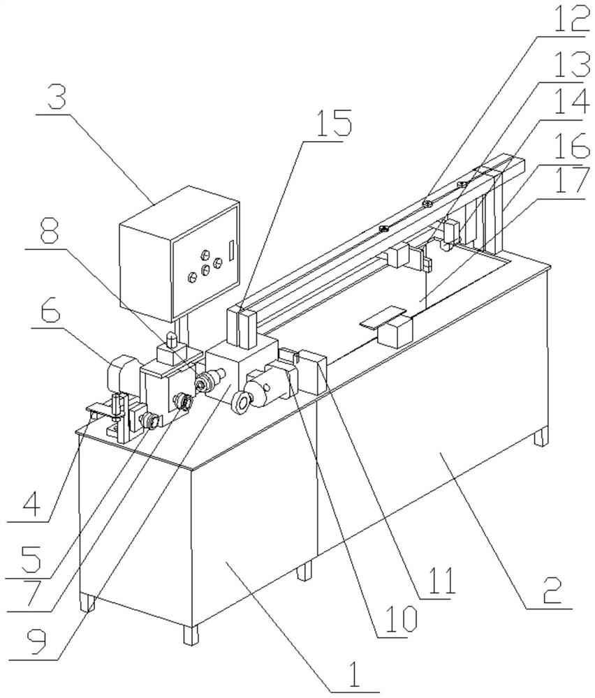
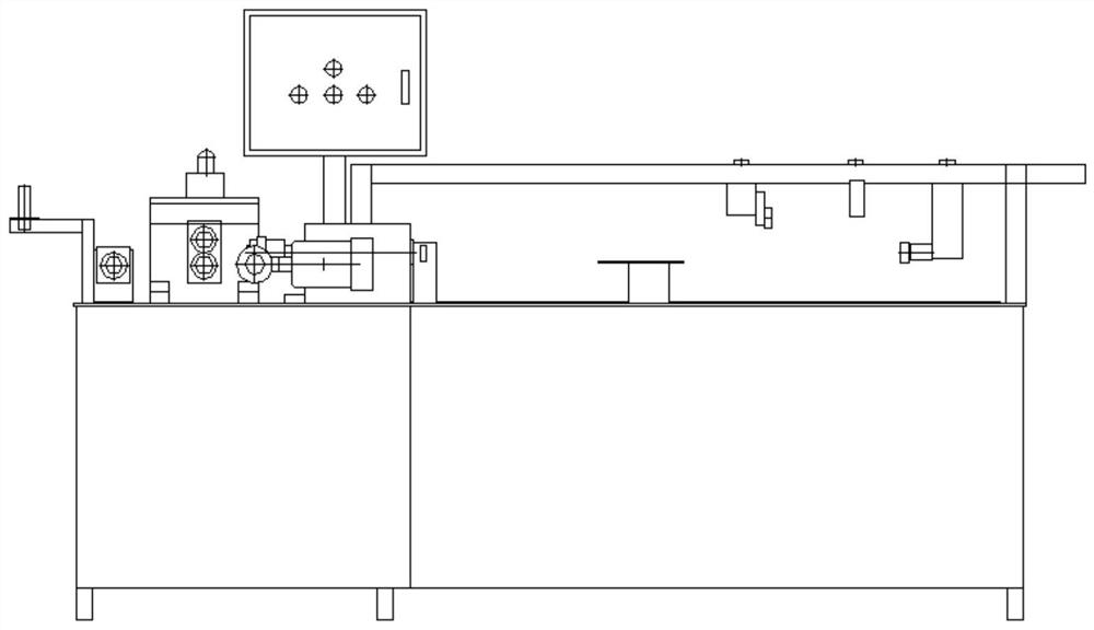
[0020] figure 1 is an axonometric view of the present invention; figure 2 It is the front view of the present invention; as figure 1 and figure 2 A kind of integrated integrated pipe cutting machine shown, comprises bedside box 1 and bedside box 2, and bedside box 1 and bedside box 2 are fixedly connected, and described bedside box 1 top outer plane is provided with feeding part, cutting part and the control electr...


PUM


Abstract

The invention discloses an integrated pipe cutting machine. The integrated pipe cutting machine comprises a machine tool head box and a machine tool tail box, wherein the machine tool head box and themachine tool tail box are fixedly connected; a feeding part, a cutting part and a control electric box are arranged on the outer plane of the top of the machine tool head box, and the feeding part, the cutting part and the control electric box are fixedly connected with the machine tool head box; a second supporting seat is arranged on the side, far away from the machine tool head box, of the outer plane of the top of the machine tool tail box, the second supporting seat is fixedly connected with the machine tool tail box, and a supporting cross beam is arranged on the second supporting seat;and the other end, far away from the second supporting seat, of the supporting cross beam is fixedly connected with the feeding part, a positioning and clamping part is arranged on the supporting cross beam, and the positioning and clamping part is fixedly connected with the supporting cross beam. By the adoption of the scheme, a machine tool is easy and convenient to operate, and a worker can carry out cutting only by carrying out simple operation on one side of the machine tool head box, so that contact between the worker and a cutting tool is avoided, and life health and safety of the worker are guaranteed.

Description

technical field [0001] The invention belongs to the field of mechanical equipment, and more specifically, the invention relates to an integrated pipe cutting machine and a use method thereof. Background technique [0002] Most of the pipe cutting machines on the market are hydraulic pipe cutting machines. The principle is that through the mutual cooperation of air and oil, the electrical system controls the movement direction of the air pressure system, and pushes the oil circuit to make a linear reciprocating movement. During the reciprocating movement, Based on the signal detected by the carriage limit, control and change the movement of the gas and oil circuits, so as to achieve the expected cutting route for pipe cutting. However, this hydraulic pipe cutting machine needs to be re-cut every time it cuts. Install pipes and restart and shut down the system, and the cutting size must be calculated and marked every time when cutting, the cutting process is very cumbersome. ...

Claims


Application Information

Patent Timeline
Patent Type & Authority Applications(China)
IPC IPC(8): B23Q7/00B23Q7/05B23Q3/06
CPCB23Q3/06B23Q7/00B23Q7/05
Inventor 石中平董怀苏苗花董枫董文誉
Owner 芜湖立新清洁用品有限公司
Why Eureka
Try Eureka