
A dryer for the production and processing of capacitor shells

A dryer and capacitor technology, applied in the field of capacitors, can solve problems such as capacitor leakage, capacitor leakage, oil leakage, capacitor shell rupture, etc., and achieve the effect of preventing moisture from remaining in the

Active Publication Date: 2022-01-11
山东泰开电力电子有限公司
View PDF0 Cites 0 Cited by
  • Summary
  • Abstract
  • Description
  • Claims
  • Application Information

AI Technical Summary

Problems solved by technology

[0002] As a basic accessory for the safe operation of the power grid, capacitors have strict production standards. Capacitor leakage and oil leakage are common faults. This is because the structure of the product has already caused irreversible damage during processing. It exists during the manufacturing process. Any defect can cause capacitor leakage. A large part of the reason is that the capacitor shell contains a certain amount of moisture inside during processing. If it remains in the shell for a long time, the paint layer will peel off and the iron sheet will be corroded, which will cause the capacitor shell to crack and leak. Leakage, and the appearance of moisture is often caused by the fact that when the capacitor shell is drying, the temperature evaporates the water and at the same time makes a part of the water vapor re-attach to the shell structure. Based on the above premise, this case developed a capacitor shell production machined dryers to solve this problem

Method used


Image

  • A dryer for the production and processing of capacitor shells
  • A dryer for the production and processing of capacitor shells
  • A dryer for the production and processing of capacitor shells

Examples


Embodiment

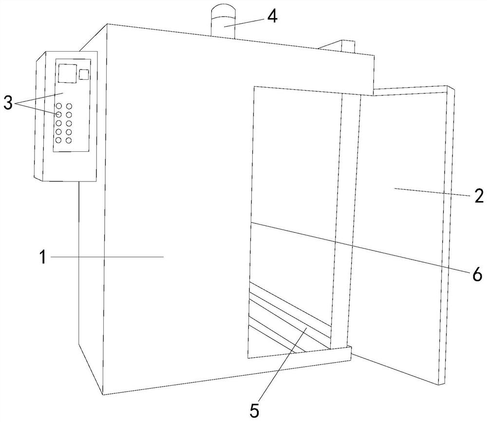
[0023] see figure 1 , the present invention provides a drying machine for the production and processing of capacitor shells, the structure of which includes: a cabinet 1, an insulated box door 2, a controller 3, an exhaust pipe 4, a slide pipe 5, and a drying rack 6. The side of the cabinet 1 is provided with an insulated box door 2 and a controller 3 respectively. The exhaust pipe 4 runs through the cabinet 1. The cabinet 1 is equipped with a slide pipe 5 and a drying rack 6. The cabinet 1 is the main body of the dryer. Its overall appearance is a hollow cuboid, which also includes the shell structure of the equipment. After the insulated box door 2 is closed, it forms a closed space with the chassis 1, which can effectively prevent heat loss, and based on its high-strength insulation made of the same material as the chassis 1 The temperature performance can block most of the heat in the case 1 during the period of time when the case 1 is closed to prevent heat from being tr...

Embodiment 2

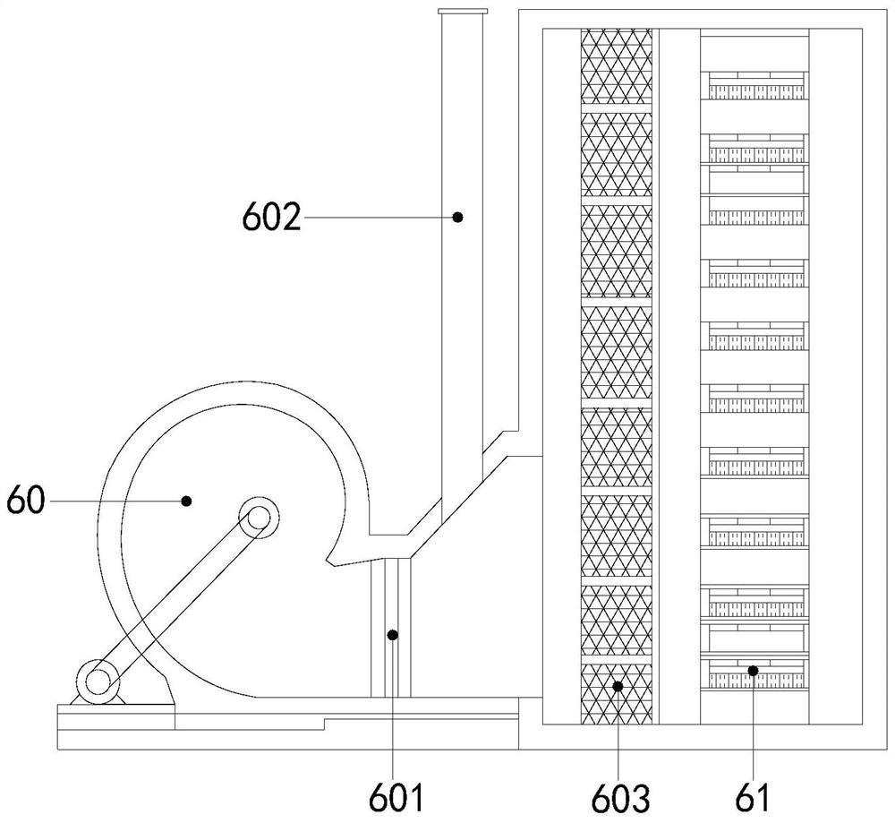
[0029] The description of the second embodiment drawn in conjunction with the first embodiment, combined with image 3 , Figure 4 and Figure 5 , the bottom of the touch-press upper seat 610 is connected to the magnetic sliding lower seat 611 at intervals, and the magnetic sliding lower seat 611 runs through and connects the dehumidification ring 612. The air jet swirl 6120 is located at the bottom of the upward swivel fan 6220 and the two are connected to each other. The side of the turning shaft 622a is annularly provided with an inflatable bag 622b. The surface of the inflatable bag 622b is distributed with a water-absorbing brush 622c and a drainage brush is arranged inside it. 622d, when the equipment is at a relatively stable and constant temperature, lay the capacitor case flat on the drying rack 6, and lift the capacitor case by means of the repulsive magnetic field formed between the touch-press upper seat 610 and the magnetic sliding lower seat 611, and at the same...


PUM


Abstract

The invention discloses a drying machine for producing and processing capacitor shells. Its structure includes: a machine case, a temperature-insulating box door, a controller, an exhaust pipe, a sliding pipe, and a drying rack. The door of the insulated box and the controller, the exhaust pipe runs through the chassis, and there are sliding pipes and drying racks in the chassis. The beneficial effect of the present invention is that the frictional water absorption method is used to frictionally contact the capacitor shell with the water-absorbing brush and the water droplets precipitated on the surface. Combining the water droplets into the water-absorbing brush and evaporating, avoiding the moisture from adhering to the capacitor casing again during the operation of the upward rotary fan, effectively preventing the capacitor casing from regaining moisture and remaining in the casing.

Description

technical field [0001] The invention relates to the field of capacitors, in particular to a dryer used for the production and processing of capacitor shells. Background technique [0002] As a basic accessory for the safe operation of the power grid, capacitors have strict production standards. Capacitor leakage and oil leakage are common faults. This is because the structure of the product has already caused irreversible damage during processing. It exists during the manufacturing process. Any defects can cause capacitor leakage. A large part of the reason is that the capacitor shell contains a certain amount of moisture inside during processing. If it remains in the shell for a long time, the paint layer will peel off and the iron sheet will be corroded, which will cause the capacitor shell to crack and leak. Leakage, and the appearance of moisture is often caused by the fact that when the capacitor shell is drying, the temperature evaporates the water and at the same time...

Claims


Application Information

Patent Timeline
Patent Type & Authority Patents(China)
IPC IPC(8): H01G13/04H01G2/10F26B5/14F26B21/00
CPCH01G13/04H01G2/10F26B5/14F26B21/004
Inventor 黄有寿
Owner 山东泰开电力电子有限公司
Learn More