Target detection method based on laser radar and image video fusion

A laser radar and target detection technology, applied in image enhancement, image analysis, image data processing, etc., can solve the problems of increased false detection rate and decreased detection accuracy rate, so as to reduce false detection rate, enhance robustness, The effect of improving the detection accuracy

Pending Publication Date: 2020-11-17
WOOTION TECH
View PDF1 Cites 8 Cited by
  • Summary
  • Abstract
  • Description
  • Claims
  • Application Information

AI Technical Summary

Problems solved by technology

[0005] The invention provides a target detection method for laser radar and image video fusion, which solves the problems of illumination, resolution, method multiples, camera focus and motion because a single image can only provide pixel information of a two-dimensional image plane at a certain moment. The impact is greater, which will lead to technical problems such as a decrease in detection accuracy and an increase in false detection rate

Method used


Image

  • Target detection method based on laser radar and image video fusion
  • Target detection method based on laser radar and image video fusion
  • Target detection method based on laser radar and image video fusion

Examples


Embodiment 1

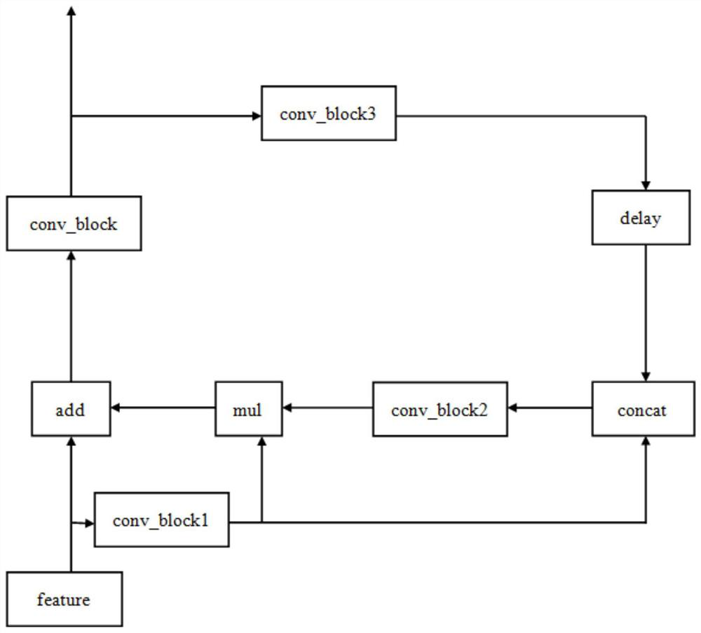
[0047] An embodiment of a target detection method for laser radar and image and video fusion in the present invention is basically as attached figure 1 shown, including steps:

[0048] S1. Fix the relative position of the image sensor and the lidar, and ensure that the image sensor and the lidar have a common view area;

[0049] S2. The image sensor collects image and video data, the laser radar collects 3D point cloud data, and the two data collections maintain real-time synchronization;

[0050] S3. Calibrate both the image video data and the three-dimensional point cloud data, and obtain the mapping relationship matrix T from the laser point cloud to the pixel plane;

[0051] S4. Obtain each frame of image data and point cloud data sequentially through the data interface in real time, run the algorithm and calculate the detection result by fusing the two-way data according to the mapping relationship matrix T;

[0052] S5. Outputting the detection result.

[0053] The sp...

Embodiment 2

[0072] The only difference from Embodiment 1 is that when the focus of the camera is suddenly blurred due to movement, or the area occupied by the dynamic object becomes smaller due to the change from near to far, a pre-judgment is made to determine whether the focus of the camera is suddenly blurred or the dynamic Is the area occupied by the target smaller in the frame due to the movement of the lens or the movement of the object being photographed. Specifically, set the reference object in advance to determine whether there is relative motion between the camera or the captured object and the reference object: if there is relative motion between the camera and the reference object, it means that the focus of the camera is suddenly blurred or the dynamic target is in the frame. The smaller occupied area is caused by the movement of the lens. At this time, adjust the static posture of the camera to keep it still; on the contrary, if there is relative motion between the captured ...


PUM


Abstract

The invention relates to the technical field of image detection, in particular to a target detection method based on laser radar and image video fusion, which comprises the steps of S1, fixing the relative positions of an image sensor and a laser radar, and ensuring that the image sensor and the laser radar have a common view area; S2, collecting image video data by the image sensor, and collecting three-dimensional point cloud data by the laser radar, wherein real-time synchronization of two paths of data collection is kept; S3, calibrating the image video data and the three-dimensional pointcloud data, and obtaining a mapping relation matrix T from the laser point cloud to a pixel plane; S4, sequentially acquiring each frame of image data and point cloud data in real time through a datainterface, operating an algorithm, and fusing the two paths of data according to the mapping relation matrix T to calculate a detection result; and S5, outputting the detection result. According to the invention, the technical problems of reduced detection accuracy and increased false detection rate due to the fact that a single image can only provide pixel information of a two-dimensional imageplane are solved.

Description

technical field [0001] The invention relates to the technical field of image detection, in particular to a target detection method for laser radar and image video fusion. Background technique [0002] In image-based target detection, the traditional method is to apply a common deep neural network structure to a single image to locate, identify and classify the target area of ​​interest. The detection accuracy and false detection rate of this method are not ideal, especially for small targets. , detection of occluded targets, blurred images, and images with too dark and too strong light. [0003] For example, document CN110175576A discloses a driving vehicle visual detection method combined with laser point cloud data. First, the joint calibration of the laser radar and the camera is completed, and then time alignment is performed; Flow grayscale image, and perform motion segmentation based on the optical flow grayscale image to obtain the motion area, that is, the candidate...

Claims


Application Information

Patent Timeline
IPC IPC(8): G06T7/292G06T7/80G01S7/48G06N3/04
CPCG06T7/292G06T7/85G01S7/4802G06T2207/10012G06N3/045
Inventor 晁战云罗元泰袁洪跃冉茂国黄秀华万钟平赖晗
Owner WOOTION TECH
Why Eureka
Try Eureka