A carbon source dosing method and system for a denitrification filter system

A denitrification filter and carbon source technology, applied in the field of water treatment, can solve problems such as large cumulative deviation, increased effluent COD risk, carbon source waste, etc., to solve cumulative deviation and lag problems, and to adaptively control carbon source input The effect of increasing, efficient and stable operation

Active Publication Date: 2021-05-28
SHENZHEN QINGQUAN WATER IND CO LTD
View PDF9 Cites 2 Cited by
  • Summary
  • Abstract
  • Description
  • Claims
  • Application Information

AI Technical Summary

Problems solved by technology

The first carbon source dosing method has a large cumulative deviation. In order to make the effluent discharge up to the standard, the amount of carbon source dosing is usually controlled to be particularly large, resulting in waste of carbon sources and easily causing the effluent COD to exceed the standard.
The second carbon source dosing method is developed on the basis of the first method. In order to solve the problem of large cumulative deviation of carbon sources in the front feedback control and save carbon source dosing, the post-feedback control is adopted, but this method There is a lag problem. Once the standard is exceeded, various correction values ​​need to be artificially set to increase the dosage of carbon sources. At the same time, it also increases the risk of effluent COD exceeding the standard.
[0004] However, high-standard discharge of sewage treatment plants is imperative, and indicators such as COD and TN of the effluent are required to be controlled at a low level. Once the carbon source dosage of the denitrification filter is not well controlled, it is easy to cause the effluent quality to exceed the standard.
Therefore, there is a need for a more stable carbon source dosing method for denitrification filters, which can effectively overcome the problem of excessive COD in the effluent caused by excessive carbon source dosing

Method used


Image

  • A carbon source dosing method and system for a denitrification filter system
  • A carbon source dosing method and system for a denitrification filter system

Examples


Embodiment

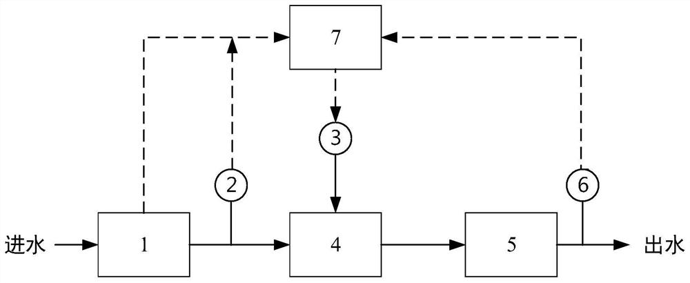
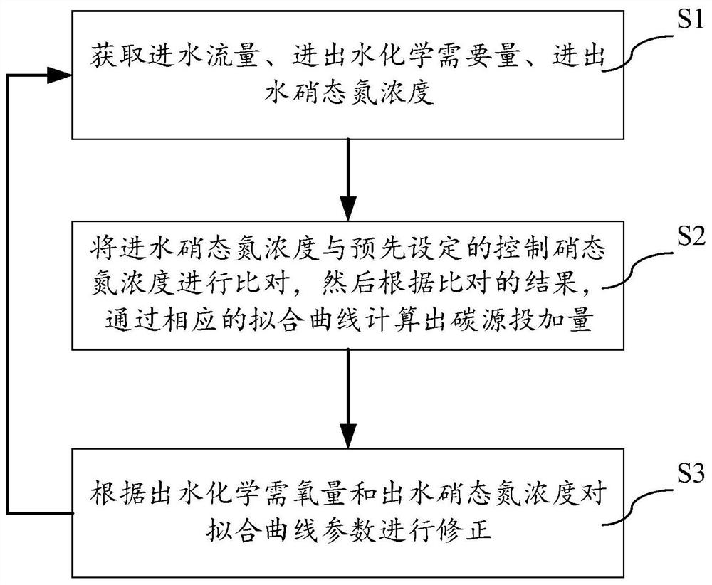
[0037] An embodiment of the denitrification filter carbon source dosing system of the present invention, the system structure schematic diagram of this embodiment is as follows figure 1 As shown, it includes a flow meter 1, a first online water quality analyzer 2, a carbon source dosing device 3, a pipeline mixer 4, a denitrification filter 5, a second online water quality analyzer 6 and an automatic control system 7; A flow meter 1 and a first online water quality analyzer 2 are set on the water inlet of the nitrification filter 5, a second online water quality analyzer 6 is set on the water outlet of the denitrification filter 5, and a second online water quality analyzer 6 is set on the denitrification filter 5. An automatic control system 7, the automatic control system 7 is electrically connected with the carbon source dosing device 3, and the carbon source dosing device 3 is connected with the denitrification filter 5 through the pipeline mixer 4; the first online The wa...


PUM


Abstract

The invention discloses a carbon source dosing method for a denitrification filter tank system, comprising the following steps: S1, obtaining the influent flow rate of the filter tank, the concentration of nitrate nitrogen in the influent water, and the chemical oxygen demand in the influent water; Fit the curve to calculate the dosage of carbon source; S3, return to S1 to cycle. The method of the present invention combines feed-forward control and feed-back control, and by introducing the variation coefficient of the carbon source consumed in the removal of nitrate nitrogen and the variation coefficient of the chemical oxygen demand of the incoming and outgoing water, it can well solve the problem of the carbon source caused by the fluctuation of water quantity and quality. The cumulative deviation and lag problems in the dosing system can realize the precise dosing of carbon sources in the denitrification filter system and ensure the efficient and stable operation of the sewage treatment plant. The invention also discloses a system using the method for adding carbon source to the denitrification filter of the invention.

Description

technical field [0001] The invention relates to the technical field of water treatment, in particular to a method and system for adding carbon sources to a denitrification filter tank system. Background technique [0002] With domestic sewage treatment plants upgrading and upgrading, the sewage discharge standards are getting higher and higher, and some even require to meet the high discharge standards of quasi-category IV or quasi-category III on the surface. At present, denitrification filters are usually used in the sewage treatment process for high discharge standards. Since the sewage has undergone secondary biochemical treatment, the organic matter has been exhausted, so the denitrification filter requires an additional carbon source to achieve nitrogen removal. [0003] There are two main methods of carbon source dosing that are popular nowadays. The first one is forward feedback control, which is mainly based on the influent flow rate and influent nitrate nitrogen c...

Claims


Application Information

Patent Timeline
Patent Type & Authority Patents(China)
IPC IPC(8): C02F3/28
CPCC02F3/28C02F2305/06
Inventor 叶昌明伍波彭金城赖正泉王小林陈红继
Owner SHENZHEN QINGQUAN WATER IND CO LTD
Why Eureka
Try Eureka