
Multi-functional pneumatic file device

A multi-functional and file technology, which is applied to other manufacturing equipment/tools, manufacturing tools, etc., can solve the problems that cannot be applied to the machining environment, etc., and achieve the effect of exquisite design structure, convenient operation and simple operation

Active Publication Date: 2020-11-17
东风汽车动力零部件有限公司
View PDF5 Cites 3 Cited by
  • Summary
  • Abstract
  • Description
  • Claims
  • Application Information

AI Technical Summary

Problems solved by technology

However, the pneumatic file structure of the existing structure is usually a reciprocating file. For more and more complex machining situations, the existing reciprocating file can no longer be used in a large number of complex machining environments. It is necessary to develop File structure with multiple functions

Method used


Image

  • Multi-functional pneumatic file device
  • Multi-functional pneumatic file device
  • Multi-functional pneumatic file device

Examples


Embodiment Construction

[0030] The present invention will be further described in detail below in conjunction with the accompanying drawings and specific embodiments.

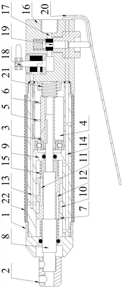
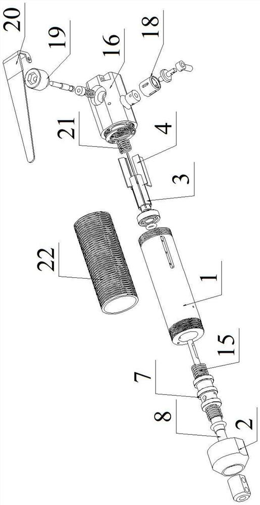
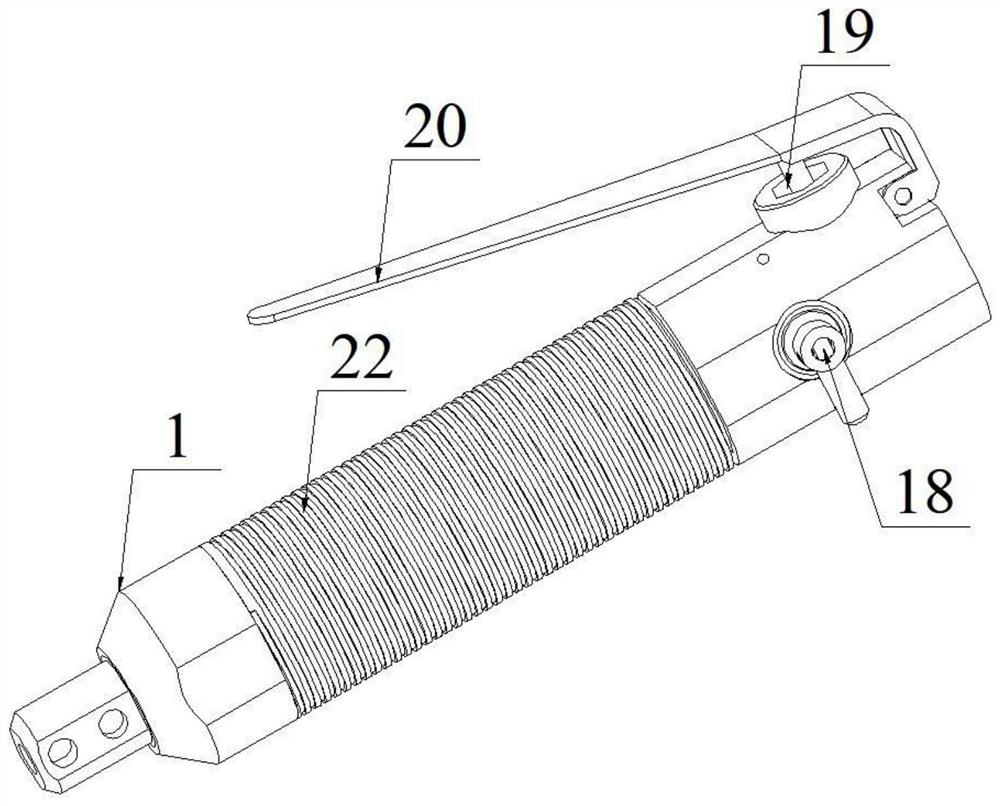
[0031] Such as Figure 1~4 As shown, the file device of this embodiment includes a housing 1, which is a hollow cylindrical structure, and a partition 9 is arranged in the housing 1 to divide the inner cavity of the housing 1 into two independent cavities, one cavity One body is used to arrange the reciprocating drive structure, and the other cavity is used to arrange the rotary drive structure. An anti-slip sleeve 22 is provided on the outside of the circumference of the housing 1 for easy gripping. One end of the housing 1 is provided with a flat plate for easy installation and clamping, and the other end is provided with a threaded structure for easy connection with the back cover 16 .

[0032] The reciprocating drive structure of this embodiment includes a piston 7 and a piston rod 8. The piston 7 is an annular structure fixed on...


PUM


Abstract

The invention relates to the technical field of machining device structures, in particular to a multi-functional pneumatic file device. The multi-functional pneumatic file device comprises a shell anda clamping sleeve, and is characterized in that a reciprocating driving structure for driving the clamping sleeve to move in an axial direction of the shell and a rotating driving structure for driving the reciprocating driving structure and the clamping sleeve to rotatably move around the axis of the shell are arranged in the shell; the clamping sleeve and the rotating driving structure are fixed to the two ends of the reciprocating driving structure respectively; and the shell is provided with an air channel respectively communicating with the reciprocating driving structure and the rotating driving structure. The multi-functional pneumatic file device comprises a shell and a clamping sleeve, and is characterized in that a reciprocating driving structure for driving the clamping sleeveto move in an axial direction of the shell and a rotating driving structure for driving the reciprocating driving structure and the clamping sleeve to rotatably move around the axis of the shell are arranged in the shell; the clamping sleeve and the rotating driving structure are fixed to the two ends of the reciprocating driving structure respectively; and the shell is provided with an air channel respectively communicating with the reciprocating driving structure and the rotating driving structure.

Description

technical field [0001] The invention relates to the technical field of machining device structures, in particular to a multifunctional pneumatic file device. Background technique [0002] At present, the files on the market are divided into manual files, pneumatic files and electric files according to the power source, and there are rotary or reciprocating files according to the movement mode. Among them, the pneumatic type can reduce the labor intensity of the operator, and the efficiency is higher than that of the manual type. However, the pneumatic file structure of the existing structure is usually a reciprocating file. For more and more complex machining situations, the existing reciprocating file can no longer be used in a large number of complex machining environments. It is necessary to develop File structure with multiple functions. Contents of the invention [0003] The purpose of the present invention is to solve the technical problems mentioned in the above-m...

Claims


Application Information

Patent Timeline
Patent Type & Authority Applications(China)
IPC IPC(8): B23P23/04
CPCB23P23/04
Inventor 陈强周惠芳汪铁云梁朔
Owner 东风汽车动力零部件有限公司
Learn More