Combined straw collector
A collector and combined technology, applied in the direction of loaders, agricultural machinery and implements, cutting equipment, etc., can solve the problems of high throwing height, high operation efficiency, low throwing height, etc. High efficiency and the effect of reducing the conveying process
- Summary
- Abstract
- Description
- Claims
- Application Information
AI Technical Summary
Problems solved by technology
Method used
Image
Examples
Embodiment 1
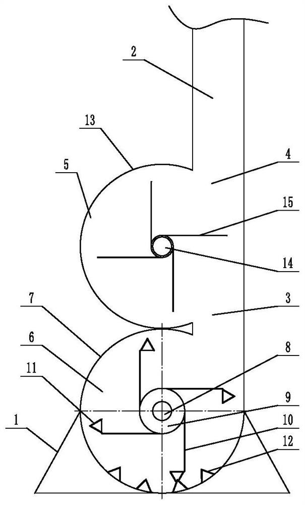
[0044] Embodiment 1: A kind of combined straw collector (see attached figure 1 ), including the feed cover 1, the throwing pipe 2, the fan combination unit installed between the feed cover and the throwing pipe, the fan combination unit includes two collection fans arranged up and down, and the collection fan is provided with a grass inlet 3 And the grass outlet 4, at least one collecting fan grass inlet is connected with the feeding hood, at least one collecting fan’s grass outlet is connected with the throwing pipe, the opening of the feeding hood is set downwards, and the collecting fan is arranged on the straw in the feeding hood. Collect and throw the straw to the throwing pipe, so that the straw is thrown outward from the throwing pipe.
[0045] The collecting fan above is the throwing fan 5, and the collecting fan below is the chopping fan 6. The grass inlet of the chopping fan is connected with the feed cover, and the grass outlet of the chopping fan is connected with ...
Embodiment 2
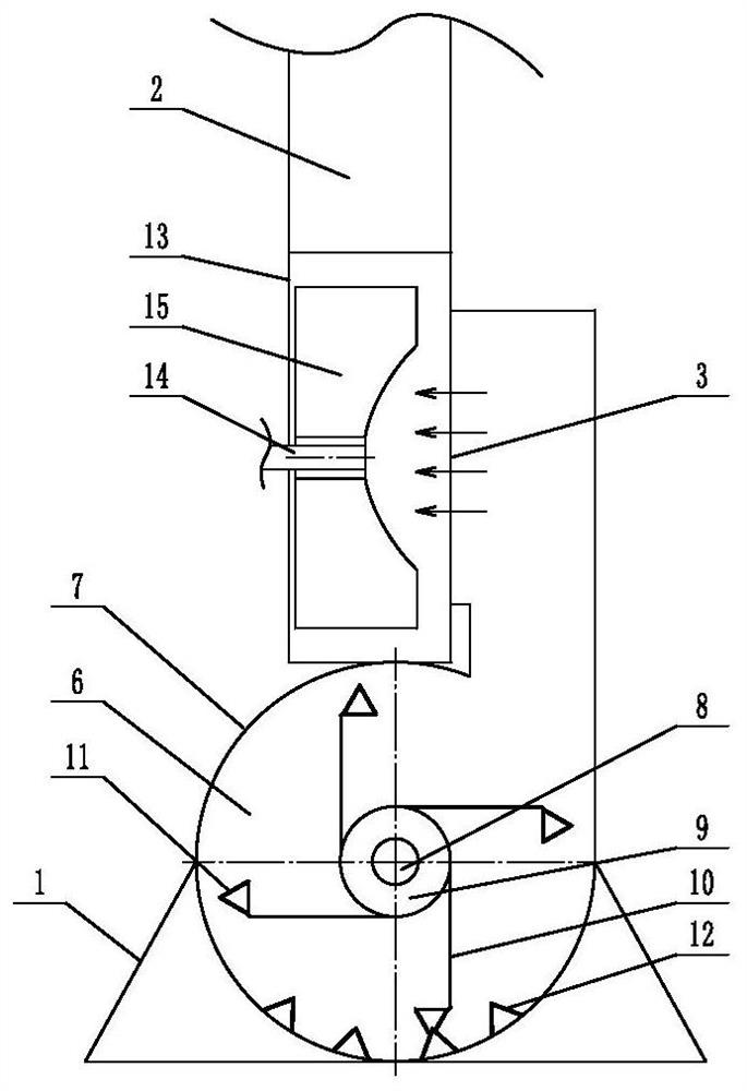
[0050] Embodiment 2: A kind of combined straw collector (see attached figure 2 ), its structure is similar to that of Embodiment 1, the main difference is that in this embodiment, the upper collection fan end face is provided with an axial feeding grass inlet, that is to say, the throwing blower adopts the axial feeding method, and the throwing blower in the throwing blower The throwing blade has a concave arc structure towards the edge of the grass inlet. Other structures are the same as in Embodiment 1.
Embodiment 3
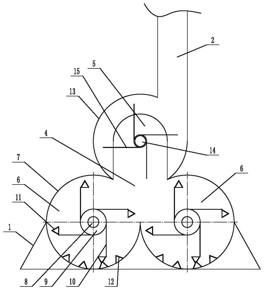
[0051] Embodiment 3: A kind of combined straw collecting machine (see attached image 3 ), including the feeding cover 1, the throwing pipe 2, the fan combination unit installed between the feeding cover and the throwing pipe, the fan combination unit includes three collecting fans, and the collecting fan is provided with a grass inlet 3 and a grass outlet Port 4, at least one collecting fan grass inlet is connected with the feeding hood, at least one collecting fan grass outlet is connected with the throwing pipe, the opening of the feeding hood is set downward, and the collecting fan collects the straw in the feeding hood and Throw the straw to the throwing pipe, so that the straw is thrown out from the throwing pipe
[0052] Two collecting fans are arranged side by side in the lower part of the fan combination unit, and one collecting fan is arranged in the upper part. The two collecting fans in the unit are chopping fans.
[0053] The chopping fan includes a casing 7, a ...
PUM
 Abstract
Description
Claims
Application Information
 - R&D
- Intellectual Property
- Life Sciences
- Materials
- Tech Scout
- Unparalleled Data Quality
- Higher Quality Content
- 60% Fewer Hallucinations
Browse by: Latest US Patents, China's latest patents, Technical Efficacy Thesaurus, Application Domain, Technology Topic, Popular Technical Reports.
© 2025 PatSnap. All rights reserved.Legal|Privacy policy|Modern Slavery Act Transparency Statement|Sitemap|About US| Contact US: help@patsnap.com


