
Broadband non-contact circular waveguide rotary joint and design method

A rotary joint, non-contact technology, applied in the microwave field, can solve the problems of wear and rotation of circular waveguide rotary joints, unable to meet the requirements of frequency changes, narrow working bandwidth, etc., to achieve wide working bandwidth, good standing wave and insertion loss performance, stable the effect of rotation

Active Publication Date: 2020-11-13
XIAN INSTITUE OF SPACE RADIO TECH
View PDF9 Cites 5 Cited by
  • Summary
  • Abstract
  • Description
  • Claims
  • Application Information

AI Technical Summary

Problems solved by technology

[0007] To sum up, most of the existing circular waveguide rotary joints currently use a choke groove structure, which has a narrow operating bandwidth and cannot meet the flexible frequency change requirements within a broadband range. The circular waveguide rotary joints realized by the contact structure have wear and tear unstable problem

Method used


Image

  • Broadband non-contact circular waveguide rotary joint and design method
  • Broadband non-contact circular waveguide rotary joint and design method
  • Broadband non-contact circular waveguide rotary joint and design method

Examples


Embodiment Construction

[0061] In order to make the object, technical solution and advantages of the present invention clearer, the embodiments disclosed in the present invention will be further described in detail below in conjunction with the accompanying drawings.

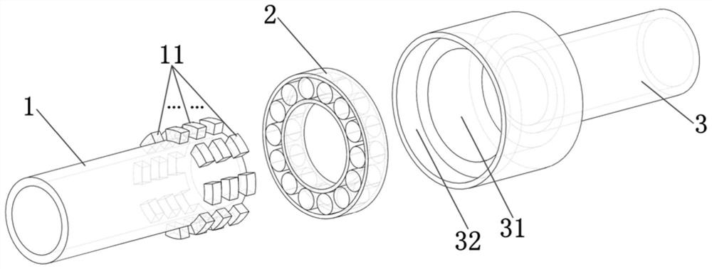
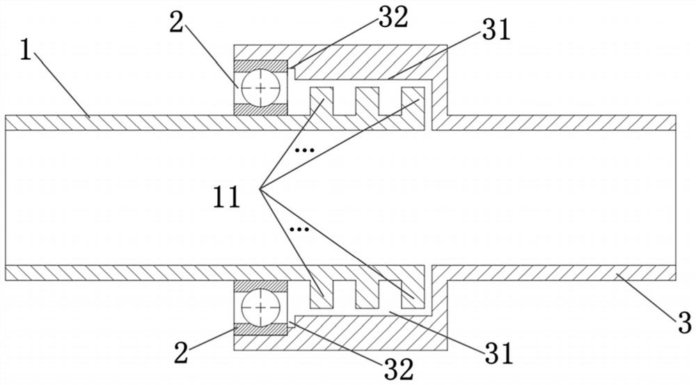
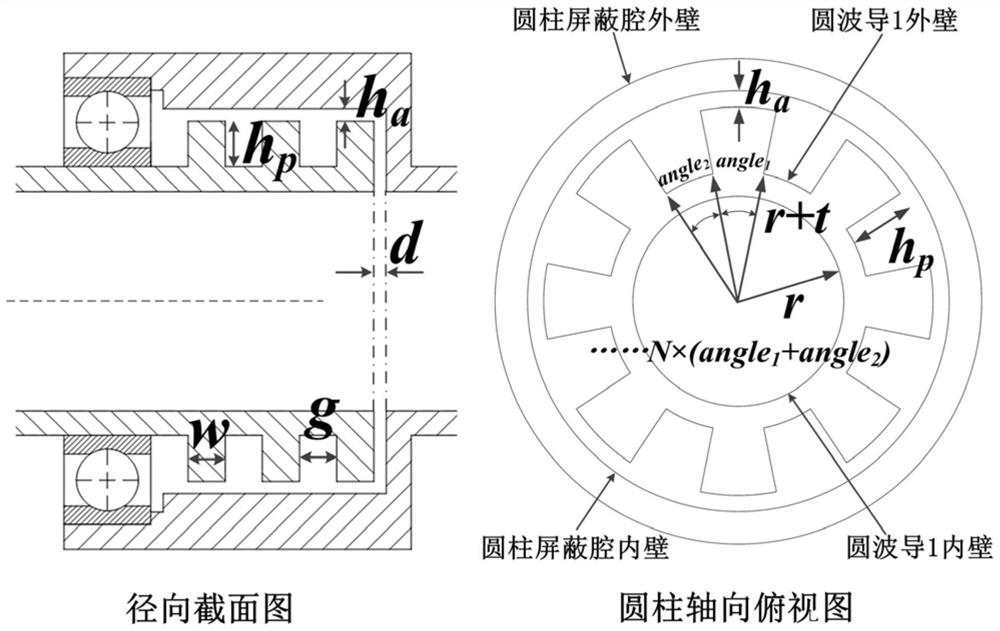
[0062] One of the core ideas of the present invention is to propose a broadband non-contact circular waveguide rotary joint, in which a number of arc-shaped metal convex bodies with equal radius are regularly arranged on the outer wall of the first circular waveguide to form a metal convex body array structure , set the corresponding shielding cavity structure at the end of the second circular waveguide, and under the premise of ensuring that the central axes of the two waveguides coincide, insert the metal convex body array part of the first circular waveguide into the shielding cavity of the second circular waveguide, and the metal convex body array The surface is not in contact with the inner wall of the shielding cavity, and a rotat...


PUM


Abstract

The invention discloses a broadband non-contact type circular waveguide rotary joint and a design method. The broadband non-contact type circular waveguide rotary joint comprises a first circular waveguide, a cylindrical surface metal convex body array, a bearing, a second circular waveguide, a shielding cavity and a bearing fixing cavity, a metal convex body array is arranged at the tail end of the first circular waveguide; a shielding cavity and a bearing fixing cavity are sequentially formed in the tail end of the second circular waveguide; the tail end of the first circular waveguide is inserted into the shielding cavity, and the first circular waveguide is not in contact with the waveguide port surface of the second circular waveguide; the metal convex body array and the shielding cavity jointly form a non-contact electromagnetic band gap structure, broadband electromagnetic shielding is achieved, and the broadband non-contact circular waveguide rotary joint is formed in cooperation with a bearing. According to the invention, the rotatable broadband non-contact electromagnetic band gap structure is constructed at the rotary joint, so that the broadband characteristic of the rotating joint is ensured, and the non-contact structure avoids abrasion, so that rotation is more stable, the service life is longer, and the rotating joint can be widely applied to various communication, radar and antenna feed systems.

Description

technical field [0001] The invention belongs to the field of microwave technology, and in particular relates to a broadband non-contact circular waveguide rotary joint and a design method. Background technique [0002] Rotary joints are important components in communication and radar antenna systems. In order to realize the continuous search, tracking and measurement of the target, it is usually required that the radiation mechanism of the antenna can realize 360° continuous rotation, and at the same time, it is necessary to ensure the uninterrupted transmission of electromagnetic signals during the rotation process. Therefore, a rotary joint must be used in the antenna feeding system to realize the connection between the fixed part and the rotating part, so as to ensure that the microwave signal can be continuously and effectively transmitted during the rotation of the antenna. [0003] Rotary joints include waveguide rotary joints and coaxial rotary joints. The waveguide...

Claims


Application Information

Patent Timeline
Patent Type & Authority Applications(China)
IPC IPC(8): H01P1/06H01P11/00
CPCH01P1/066H01P11/00
Inventor 陈翔孙冬全李军李小军崔万照胡天存黄微
Owner XIAN INSTITUE OF SPACE RADIO TECH
Learn More