A sliding thrust bearing with cam linkage to achieve load distribution between pads

A technology of sliding thrust bearing and linkage block, which is applied in the direction of sliding contact bearing, rotating bearing, bearing, etc., can solve problems such as unbalanced force, achieve uniform and stable transmission, meet reliability and stability, and ingenious structural design reasonable effect

Active Publication Date: 2021-10-15
DONGFANG TURBINE CO LTD
View PDF0 Cites 0 Cited by
  • Summary
  • Abstract
  • Description
  • Claims
  • Application Information

AI Technical Summary

Problems solved by technology

[0003] In order to solve the above-mentioned technical problem of unbalanced force between the pads of the existing sliding thrust bearing, the purpose of the present invention is to provide a sliding thrust bearing that realizes the uniform load distribution between the pads by cam linkage. The cam linkage mechanism composed of the linkage block cooperates with each tile, so that each tile can self-adaptively adjust the force through the cam linkage mechanism. The load is evenly distributed between the tiles, and finally the characteristics of force balance between the tiles are achieved

Method used


Image

  • A sliding thrust bearing with cam linkage to achieve load distribution between pads
  • A sliding thrust bearing with cam linkage to achieve load distribution between pads
  • A sliding thrust bearing with cam linkage to achieve load distribution between pads

Examples


Embodiment Construction

[0033] All features disclosed in this specification, or steps in all methods or processes disclosed, may be combined in any manner, except for mutually exclusive features and / or steps.

[0034] Any feature disclosed in this specification (including any appended claims, abstract), unless otherwise stated, may be replaced by alternative features which are equivalent or serve a similar purpose. That is, unless expressly stated otherwise, each feature is one example only of a series of equivalent or similar features.

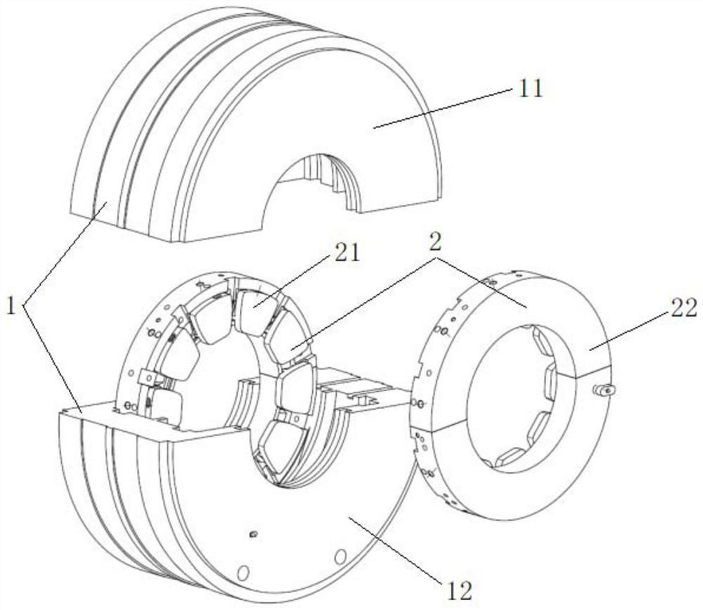
[0035] The embodiment is basically as figure 1 As shown: this embodiment provides a sliding thrust bearing that achieves uniform load distribution between pads by cam linkage, which is applied in a steam turbine to withstand the axial thrust of the rotor and limit its axial displacement; the sliding thrust bearing includes a bushing sleeve 1 and the thrust pad assembly 2, the bushing sleeve 1 includes an upper half bearing bushing 11 and a lower half bearing bushin...


PUM


Abstract

The invention discloses a sliding thrust bearing which achieves uniform load distribution between pads by means of cam linkage, and relates to the technical field of large rotating machinery bearings; it comprises a bearing bush and a thrust bush assembly, and the thrust bush assembly is installed in the bearing bush through a mounting groove; The thrust pad assembly includes a holding ring, a thrust pad and a cam linkage mechanism. The cam linkage mechanism includes a cam block and a linkage block corresponding to the thrust pad. The cam block and the linkage block are arranged in a staggered manner. and the linkage block can swing between the inner walls of the holding ring, and the two ends of the linkage block swing are respectively in contact with the adjacent cam blocks; through the implementation of this technical solution, the force between the pads of the existing sliding thrust bearing can be effectively solved Unbalanced technical problems, so that each tile can self-adaptively adjust the force through the cam linkage mechanism, while avoiding the unfavorable factors of the spherical surface, it can achieve a good load distribution between the tiles, and finally achieve The characteristics of force balance.

Description

technical field [0001] The invention relates to the technical field of large rotating machinery bearings, in particular to a sliding thrust bearing which realizes uniform load distribution between pads by means of cam linkage. Background technique [0002] At present, sliding thrust bearings are widely used in large-scale power generation equipment such as thermal power, nuclear power, and gas turbines due to their superior characteristics. To make each thrust pad receive an even force, the existing steam turbine thrust bearing usually adopts a spherical surface fit structure between the bearing pad body and the bearing pad sleeve to realize the self-positioning function of the thrust bearing, but the spherical structure requires high machining accuracy and is difficult to manufacture. The dependence of the thrust pad is extremely strong, and in actual operation, the self-alignment ability is often reduced or failed due to spherical jamming. Once the self-alignment ability f...

Claims


Application Information

Patent Timeline
Patent Type & Authority Patents(China)
IPC IPC(8): F16C17/06F16C17/12
CPCF16C17/06F16C17/12F16C2380/26
Inventor 安海阳李溶江赵卫军舒文号王丹琦
Owner DONGFANG TURBINE CO LTD
Why Eureka
Try Eureka