Rock wall crane beam structure and construction method thereof

A technology of crane beams and rock walls, which can be applied to basic structure engineering, underwater structures, artificial islands, etc., and can solve problems such as unfavorable stability of caverns, failure to meet structural safety requirements, and insufficient anchoring force

Inactive Publication Date: 2020-11-10
POWERCHINA ZHONGNAN ENG
View PDF12 Cites 0 Cited by
  • Summary
  • Abstract
  • Description
  • Claims
  • Application Information

AI Technical Summary

Problems solved by technology

This is also the reason why the code stipulates that the length of the anchorage section of conventional bonded anchors is limited. The fundamental reason is that simply increasing the length of the anchorage section cannot fundamentally solve the problem of insufficient anchoring force
If the traditional force transmission method is still used, it is still applicable when the load value is small, but when the load value is large, it cannot meet the structural safety requirements, and it is necessary to use a new force transmission method to solve the problem
From the point of view of force, whether it is a bonded anchor or an end anchor, the tensile force on the anchor is finally transmitted to the mountain, but for conventional bonded anchors, since the free section is close to the free surface , in the large underground powerhouse where the stability contradiction of the cavern is already very prominent, a large unfavorable external load is applied, which is even more unfavorable to the stability of the cavern, and this situation should be avoided to the greatest extent. The method of force will inevitably lead to the emergence of such unfavorable situations

Method used


Image

  • Rock wall crane beam structure and construction method thereof
  • Rock wall crane beam structure and construction method thereof
  • Rock wall crane beam structure and construction method thereof

Examples


Embodiment

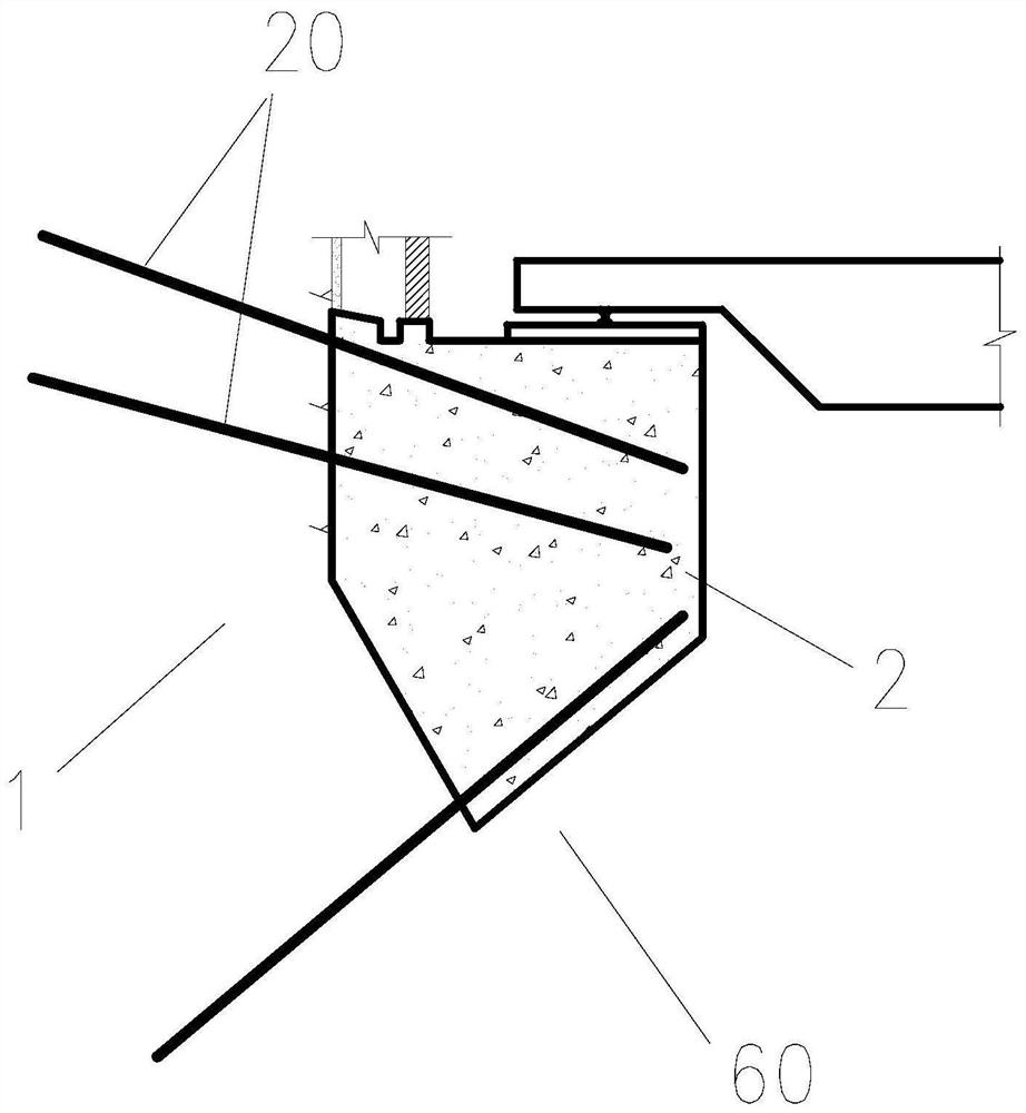
[0142] Such as Figure 4 As shown, the rock wall crane beam structure of this embodiment includes a rock wall crane beam 2 fixed on the wall surface of the surrounding rock 1 , and a plurality of prestressed anchor rods 3 connecting the surrounding rock 1 and the rock wall crane beam 2 .

[0143] The wall surface of the surrounding rock 1 is provided with anchor holes 11 corresponding to the prestressed anchor rods 3 one-to-one. The air pipe 8 and the accommodation pipe 7 run through the two walls of the rock wall crane beam 2 along the length direction of the prestressed anchor rod 3, and the inner cavity of the accommodation pipe 7 forms a through hole 21, and the anchor hole 11 communicates with the corresponding through hole 21 to form Accommodating holes.

[0144] One end of the oil injection pipe 7 is fixedly connected and communicated with the end of the accommodation pipe 6 near the anchor hole 11, and the other end of the oil injection pipe 7 is provided with an oil ...


PUM


Abstract

The invention discloses a rock wall crane beam structure and a construction method thereof. The rock wall crane beam structure comprises a rock wall crane beam fixed on a surrounding rock wall surface, and a prestressed anchor rod for connecting surrounding rock with the rock wall crane beam, wherein an anchoring hole is formed in the wall surface of the surrounding rock, a through hole penetrating through the two wall surfaces of the rock wall crane beam in the length direction of the prestressed anchor rod is formed in the rock wall crane beam, the anchoring hole and the through hole communicate to form a containing hole, an anchoring end is formed at one end of the prestressed anchor rod, a locking end is formed at the other end of the prestressed anchor rod, and a free section is formed between the anchoring end and the locking end. The anchoring end is anchored in the anchoring hole, the free section is tensioned in the containing hole, and the locking end is locked on the free surface of the rock wall crane beam. A new force transmission mode is innovatively adopted, so that tensile force is directly transmitted to the deep part of the rock wall, the cement mortar is prevented from being subjected to tension-shear action, the advantage of high compressive strength of the cement mortar in a three-way compressive stress state is brought into full play, the anchoring end isfar away from the free surface, and the stability of a cavern is effectively ensured.

Description

technical field [0001] The invention relates to the technical field of underground cavern infrastructure, in particular to a rock wall crane beam structure and a construction method thereof. Background technique [0002] In the practice of water conservancy and hydropower projects and other infrastructure-related underground caverns, the span of underground caverns is a highly sensitive control index, especially for large-span underground caverns, such as underground powerhouses, main transformer rooms, and tailgates. etc. The larger the span, the greater the difficulty of cavern structure design and the greater the safety risk. Minimizing the span of the cavern is an effective measure to ensure the stability of the underground cavern and reduce the safety risk. In order to minimize the span of the cavern or meet the layout requirements, it is necessary to cancel the rock platform of the crane beam on the rock wall in some cases. [0003] Compared with the conventional rock...

Claims


Application Information

Patent Timeline
IPC IPC(8): E02D29/045E02D5/74E02B9/00B66C7/08G06F30/17G06F30/15G06F30/20G06F119/14
CPCE02D29/045E02D5/74E02B9/00B66C7/08G06F30/17G06F30/15G06F30/20G06F2119/14Y02E10/20
Inventor 谭永华许长红覃玉兰王宏贵刘朝晖吴徐华
Owner POWERCHINA ZHONGNAN ENG
Why Eureka
Try Eureka