
Design method and making process of fibre-optical grating sensitization strain transducer

A strain sensor and fiber grating technology, applied in the field of fiber grating increase and decrease sensitive strain sensor, embedded fiber grating increase and decrease sensitive strain sensor, can solve the problem of no increase or decrease sensitivity effect and the like

Inactive Publication Date: 2006-11-29
HARBIN INST OF TECH
View PDF0 Cites 15 Cited by
  • Summary
  • Abstract
  • Description
  • Claims
  • Application Information

AI Technical Summary

Problems solved by technology

At present, from the perspective of the increase and decrease sensitivity mechanism of the sensitive element, there are no related reports and related patents to achieve the increase and decrease sensitivity effect by changing the mechanical properties

Method used


Image

  • Design method and making process of fibre-optical grating sensitization strain transducer
  • Design method and making process of fibre-optical grating sensitization strain transducer
  • Design method and making process of fibre-optical grating sensitization strain transducer

Examples


Embodiment Construction

[0031] For specific engineering applications, the following two types of fiber grating increase and decrease sensitive strain sensors are designed:

[0032] (1) For surface strain monitoring of civil engineering, adhesive fiber grating increase and decrease sensitive strain sensors are required:

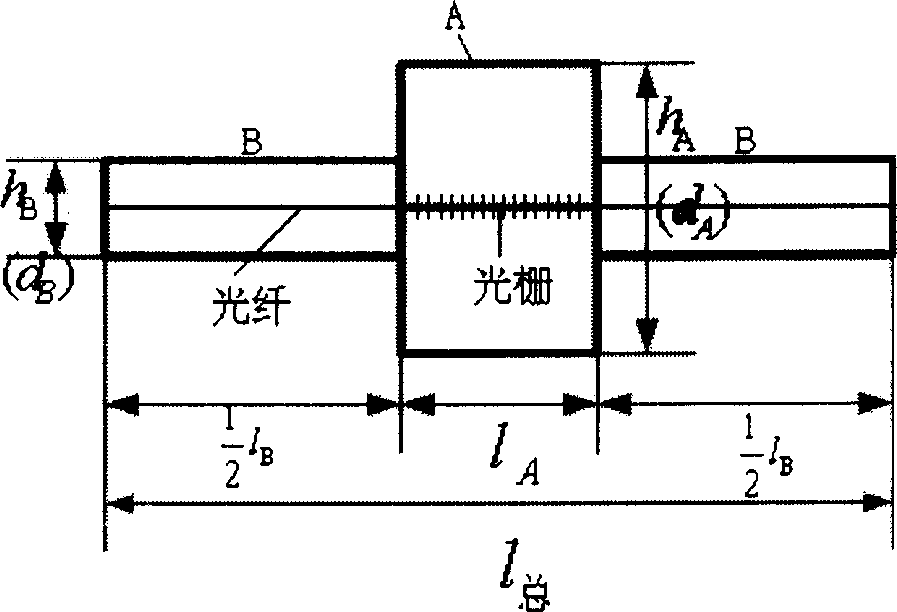
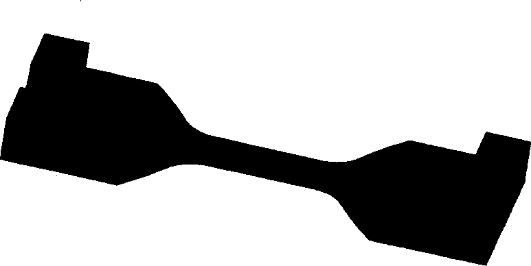
[0033] designed to be attached figure 2 , attached image 3 The flakes shown have the same thickness, then formula (3-6) becomes

[0034] K = K l + h A h B k L + 1 = K l + K h K ...


PUM

PropertyMeasurementUnit
Thicknessaaaaaaaaaa

Abstract

The invention offers the designing method and manufacturing technology for the optical fiber raster fluctuating sensitive strain gage. It includes fluctuating sensitivity theoretical derivation, enhanced sensitivity coefficient definition, material selection, and structure form determination. And it has the advantages of simple structure, low cost, variable enhanced sensitivity coefficient, and good practicality etc. It ban be used to do macro-strain and high precision measuring, especially for the monitoring of the civil engineering superficial structure and concrete built-in strain.

Description

(1) Technical field [0001] The present invention relates to a sticking type optical fiber grating increase and decrease sensitive strain sensor for steel structure surface strain measurement and an embedded optical fiber grating increase and decrease sensitive strain sensor for concrete internal strain measurement, wherein the large strain intensified sensor is used for measuring Structure cracks and concentrated stress, etc., high-precision desensitization sensors are used for small strain measurements with high precision requirements. Specifically, it is a fiber grating increase and decrease sensitive strain sensor formed by optimizing the shape of the material structure. The invention also relates to the manufacturing process of this type of sensor. (2) Background technology [0002] Regarding the increase and decrease sensitivity of fiber grating strain sensors, experts and scholars at home and abroad have conducted various studies on how to increase the sensitivity coe...

Claims


Application Information

Patent Timeline
IPC IPC(8): G01B11/16G01D5/353G01L1/24
Inventor 周智张广玉盛培军张小政欧进萍
Owner HARBIN INST OF TECH
Learn More