
Split dynamic and static dual-purpose pedicle screw and mounting tool thereof

A pedicle screw and split technology, which is applied in the field of medical devices, can solve the problems of reducing fixation strength, reducing stress concentration, and blocking the observation line of sight, so as to ensure the safety of surgery, reduce local pressure sores, and reduce pain and discomfort.

Pending Publication Date: 2020-11-06
董谢平
View PDF0 Cites 1 Cited by
  • Summary
  • Abstract
  • Description
  • Claims
  • Application Information

AI Technical Summary

Problems solved by technology

The former means that the system has sufficient rigidity and can completely limit the movement of the fixed segment. It is a static fixation method. The pedicle screw with this function is called a "fixed screw"; the latter deliberately retains the proper space between the fixed segments. It is a dynamic fixation method, in order to achieve the purpose of reducing the stress concentration of adjacent segments, and the pedicle screw body under the dynamic fixation method can still obtain dynamic activities relative to the connecting rod after the fixation operation is completed, so it is also It is called "dynamic nail", but these non-fused dynamic nails all have the disadvantages of large nail base and many parts.
[0005] In addition, at present, whether it is a static or dynamic pedicle screw, the screw base and the screw body have been assembled and integrated before the operation. When the pedicle screw is implanted, the thick screw base blocks the It is difficult for doctors to accurately judge whether the implantation depth is just right due to the observation of the relatively small screw neck. If the implantation is too deep, the tip of the screw will penetrate the front edge of the vertebral body and endanger the safety of large blood vessels, or if the implantation is too shallow, the fixation strength will be reduced. It is not uncommon in clinical
Once these situations occur, if the implantation is too shallow, the fixation rod can be removed and then screwed deeper for re-fixation, which only prolongs the operation time and increases the risk of bleeding and infection; but if the implantation is too deep and then removed, not only the above disadvantages, Back-tightening of the pedicle screw will greatly reduce the fixation strength of the screw channel and reduce the quality of the operation.

Method used


Image

  • Split dynamic and static dual-purpose pedicle screw and mounting tool thereof
  • Split dynamic and static dual-purpose pedicle screw and mounting tool thereof
  • Split dynamic and static dual-purpose pedicle screw and mounting tool thereof

Examples


Embodiment 1

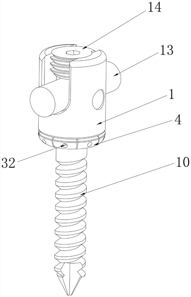
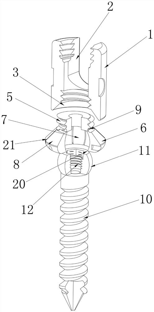
[0042] like figure 1 figure 2 As shown in the figure, the first embodiment of the present invention provides a claw-type split dynamic and static dual-purpose pedicle screw, which is composed of a screw base 1, a connecting claw 4 and a ball head screw 10, and the upper half of the connecting claw 4 is a hollow cylindrical body 5. And the outer surface is provided with an external thread, the lower half of the connecting claw 4 is an umbrella body 6, and the inside of the umbrella body 6 is provided with a spherical cavity 7 for matching with the ball head 11 of the ball stud 10. The body 6 is evenly divided into several petals 8 and can be opened outward under the action of external force. The outer surface of the intersection of the upper half and the lower half of the connecting claw 4 is also provided with an annular deformation groove 9. The upper part of the connecting claw 4 The half and the lower half are integrated;

[0043] The nail base 1 is provided with an open...

Embodiment 2

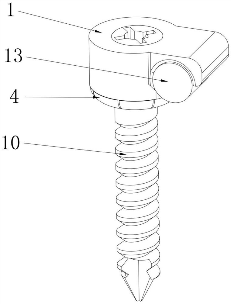
[0062] like image 3 , Figure 4 and Figure 5 As shown, the difference between the second embodiment and the first embodiment is that the structure of the nail base 1 is changed and the structure of pressing the connecting rod 13 by the locking screw 14 is eliminated, so that the structure is more compact with fewer parts.

[0063] Specifically, the second embodiment provides a hook-type split dynamic and static dual-purpose pedicle screw, which is composed of a screw base 1, a connecting claw 4 and a ball head screw 10. The upper half of the connecting claw 4 is a hollow cylindrical body 5 and The outer surface is provided with an external thread, the lower half of the connecting claw 4 is an umbrella body 6, and the inside of the umbrella body 6 is provided with a spherical cavity 7 for matching with the ball head 11 of the ball stud 10. The umbrella body 6 is divided into several petals 8 and can be opened outward under the action of external force. The outer surface of ...

Embodiment 3

[0079] like Image 6 , Figure 7 and Figure 8 As shown, the difference between the third embodiment and the second embodiment is that the threaded structure connecting the nail base 1 and the connecting claw 4 is cancelled, and an internal thread is added to the inner surface of the upper half of the connecting claw 4, and passes through the cover. The locking screw 14 is used to lock the connecting claw 4, the nail base 1 and the connecting rod 13. This structure is more convenient to operate and requires less precision in the design and processing of parts.

[0080] Specifically, a cover-type split dynamic and static dual-purpose pedicle screw is composed of a screw base 1, a connecting claw 4 and a ball head screw 10. The upper half of the connecting claw 4 is a hollow cylindrical body 5 and the outer surface is a smooth surface , the inner surface is provided with an internal thread, the lower half of the connecting claw 4 is an umbrella body 6, and the inside of the um...


PUM


Abstract

A split type dynamic and static dual-purpospedicle screw capable of being fused or fixed in a non-fused mode and assembled in an operation is used for a spinal internal fixation operation, and is composed of a screw base (1), a connecting claw (4), a ball screw (10), an auxiliary connecting rod (13) and a locking screw (14) which are assembled in the operation. The screw base (1) is provided witha circular hollow cavity, an open through groove (2) for restraining the connecting rod (13) is formed in the top end or the side wall of the screw base (1), and the lower end of the screw base (1) isan umbrella-shaped opening (3); the upper half portion of the connecting claw (4) is a hollow cylindrical body (5) connected with the screw base (1), the lower half portion of the connecting claw (4)is an umbrella-shaped body (6), an annular deformation groove (9) is formed in the outer surface of the joint, the umbrella-shaped body (6) is evenly divided into a plurality of petals (8) capable ofbeing opened outwards, and a spherical cavity (7) is formed inside. During an operation, the ball screw (10) is implanted into the pedicle of the vertebral arch, then the inner cavity of the umbrella-shaped body (6) at the lower end of the connecting claw (4) wraps the ball head part (11), the screw base (1) is sleeved in the connecting claw (4) and is connected with the connecting claw (4) through a threaded structure, and finally the connecting rod (13) is inserted into the open through groove (2) and locks threaded connection. The incisura of the pedicle screw is extremely low, so that discomfort such as pain and the like caused by muscle stimulation of a highly convex implant can be greatly reduced.

Description

technical field [0001] The invention relates to a human body implant used in orthopaedics or neurosurgery in the field of medical instruments, in particular to a split dynamic and static dual-purpose pedicle screw and an installation tool thereof. Background technique [0002] With the development of biomechanical research and material science, the application of internal fixation technology has become more and more extensive. The pedicle screw rod fixation system currently used in orthopedic surgery is composed of several pedicle screws connected to each vertebral arch. The pedicle screw is composed of the connecting rod of the root screw, and the pedicle screw is composed of a conjoined screw seat, a screw body and a separate locking screw. [0003] During the operation, firstly use tools to connect the screw bases and screw the nails into the pedicles of different vertebrae, then use connecting rods to connect the screw bases of each pedicle screw on the same side of the ...

Claims


Application Information

Patent Timeline
IPC IPC(8): A61B17/70A61B17/86A61B17/88A61B17/92
CPCA61B17/7064A61B17/7074A61B17/7002A61B17/8685A61B17/88A61B17/8605A61B17/92A61B2017/564A61B17/7037A61B17/7035A61B17/7041A61B17/7082A61B17/8615Y02A50/30A61B17/7005A61B17/7032
Inventor 董谢平何伟义李青莉张元维张霄翔余星亮
Owner 董谢平
Learn More