
Ethernet power supply equipment interface circuit and Ethernet power supply equipment

A technology for interface circuits and power supply equipment, applied in circuit devices, emergency protection circuit devices for limiting overcurrent/overvoltage, emergency protection circuit devices, etc., can solve problems affecting the life of PSE chips, heat damage, and load current imbalance And other issues

Active Publication Date: 2020-11-06
HANGZHOU HIKVISION DIGITAL TECH
View PDF19 Cites 0 Cited by
  • Summary
  • Abstract
  • Description
  • Claims
  • Application Information

AI Technical Summary

Problems solved by technology

[0004] The inventor found in the research that when the above method is adopted, the two-channel power supply of the PSE chip will cause the load current transmitted by the two channels to be unbalanced due to the PCB (Printed Circuit Board, printed circuit board) wiring and the network transformer. problem, and the greater the output power, the more obvious the imbalance of the load current, resulting in the current difference between the idle line pair and the data line pair. And it will lead to excessive output power of the PSE chip, which will affect the life of the PSE chip

Method used


Image

  • Ethernet power supply equipment interface circuit and Ethernet power supply equipment
  • Ethernet power supply equipment interface circuit and Ethernet power supply equipment
  • Ethernet power supply equipment interface circuit and Ethernet power supply equipment

Examples


Embodiment Construction

[0043] The following will clearly and completely describe the technical solutions in the embodiments of the application with reference to the drawings in the embodiments of the application. Apparently, the described embodiments are only some of the embodiments of the application, not all of them. Based on the embodiments in this application, all other embodiments obtained by persons of ordinary skill in the art without making creative efforts belong to the scope of protection of this application.

[0044] First, explain the technical terms in the embodiment of this application:

[0045] POE: refers to the transmission of data signals for some IP-based terminals (such as IP phones, wireless LAN access points, network cameras, etc.) without any changes to the existing Ethernet Cat. At the same time, it can also provide DC power supply technology for such devices. POE technology can guarantee the normal operation of the existing network while ensuring the security of the existin...


PUM


Abstract

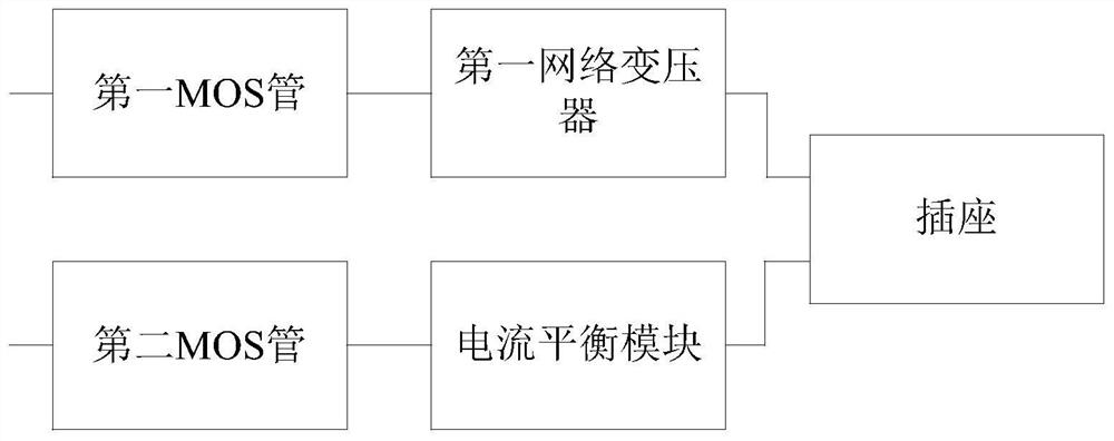
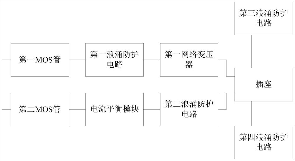
An embodiment of the invention provides an Ethernet power supply equipment interface circuit and Ethernet power supply equipment. The Ethernet power supply equipment interface circuit comprises a first MOS tube, a second MOS tube, a current balance module, a first network transformer and a socket, wherein the current balance module is used for balancing current between a data line pair of the socket and an idle line pair of the socket; the first MOS transistor is connected with a first network transformer, and the first network transformer is connected with two pairs of data line pairs of thesocket; a positive electrode of a center tap of the first network transformer is connected with a POE positive electrode port, and a negative electrode of the center tap of the first network transformer is connected with a first PSE negative electrode port; and the second MOS transistor is connected with the current balance module, and the current balance module is connected with the idle line pair of the socket. According to the Ethernet power supply equipment interface circuit, the balance of the current power of two channels is realized, the situation that the single-path output power of the PSE chip is too large is reduced, the service life of the PSE chip is prolonged, and the heating and damage situations caused by the fact that the current is too large by a single-path line are reduced.

Description

technical field [0001] The present application relates to the technical field of Ethernet power supply, in particular to an interface circuit of Ethernet power supply equipment and Ethernet power supply equipment. Background technique [0002] POE (Power Over Ethernet, Power Over Ethernet) refers to the power supply for some IP-based terminals (such as IP phones, wireless access points) without any changes to the existing Ethernet Cat.5 cabling infrastructure. , network cameras, etc.) while transmitting data signals, it can also provide DC power supply technology for such devices. A complete POE system includes two parts: PSE (Power Sourcing Equipment, power supply equipment) and PD (Powered Device, power receiving equipment). The PSE device is a device that supplies power to Ethernet client devices, and is also the manager of the entire POE power supply process. The PD device is the PSE load receiving power supply, that is, the client device of the POE system. [0003] I...

Claims


Application Information

Patent Timeline
IPC IPC(8): H04L12/10H02H9/00
CPCH04L12/10H02H9/005
Inventor 杨洋
Owner HANGZHOU HIKVISION DIGITAL TECH
Learn More