Tail gas treatment device for fuel cell system and fuel cell system
A fuel cell system and tail gas treatment technology, applied in fuel cells, electrical components, circuits, etc., can solve problems such as increased risk of explosion and excessive hydrogen concentration, and achieve the effect of improving overall safety and reducing concentration
- Summary
- Abstract
- Description
- Claims
- Application Information
AI Technical Summary
Problems solved by technology
Method used
Image

Examples
Embodiment 1
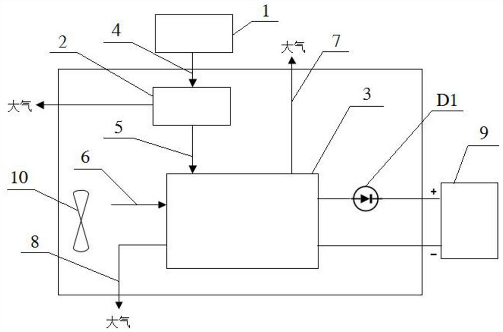
[0032] see figure 1 As shown, the embodiment of the present invention provides an exhaust gas treatment device for a fuel cell system, wherein the fuel cell system includes a first fuel cell stack 1, and the exhaust gas treatment device Z1 includes a second gas-water separator 2 and a second fuel cell Stack 3; the second gas-water separator 2 is connected with the second anode hydrogen inlet pipe 4 and the first anode hydrogen outlet pipe 5, and the second gas-water separator 2 obtains the first fuel cell stack 1 through the second anode hydrogen inlet pipe 4 The gas-liquid mixture in the second gas-water separator 2 passes through the first anode hydrogen outlet pipe 5 into the second fuel cell stack 3, and unused water and nitrogen flow into the atmosphere; the second fuel cell The stack 3 is communicated with a second cathode inlet pipe 6, a second anode hydrogen outlet pipe 7 and a second cathode outlet pipe 8, and the second fuel cell stack 3 obtains air in the atmosphere...
Embodiment 2
[0036]Its basic content is the same as embodiment 1, and the difference is:
[0037] The exhaust gas treatment device Z1 also includes a storage battery 9, which is connected to the second fuel cell stack 3 through a diode D1 and a wire harness, and the voltage of the storage battery 9 is lower than that of the second fuel cell stack 3, and the second fuel cell stack 3 is connected to the fuel cell stack 3. After the hydrogen gas discharged from the anode of the system is recycled and reused, the generated electric energy can directly charge the storage battery 9, which improves the utilization efficiency of hydrogen gas.
[0038] Since the second fuel cell stack 3 is directly connected to the storage battery 9, and the fuel cell has a one-way output characteristic (that is, it can only output, but cannot be input), it is necessary to set the total voltage in the second fuel cell stack 3 higher than that of the vehicle battery 9, the battery 9 can be charged, otherwise the fue...
Embodiment 3
[0042] Its basic content is the same as embodiment 1, and the difference is:
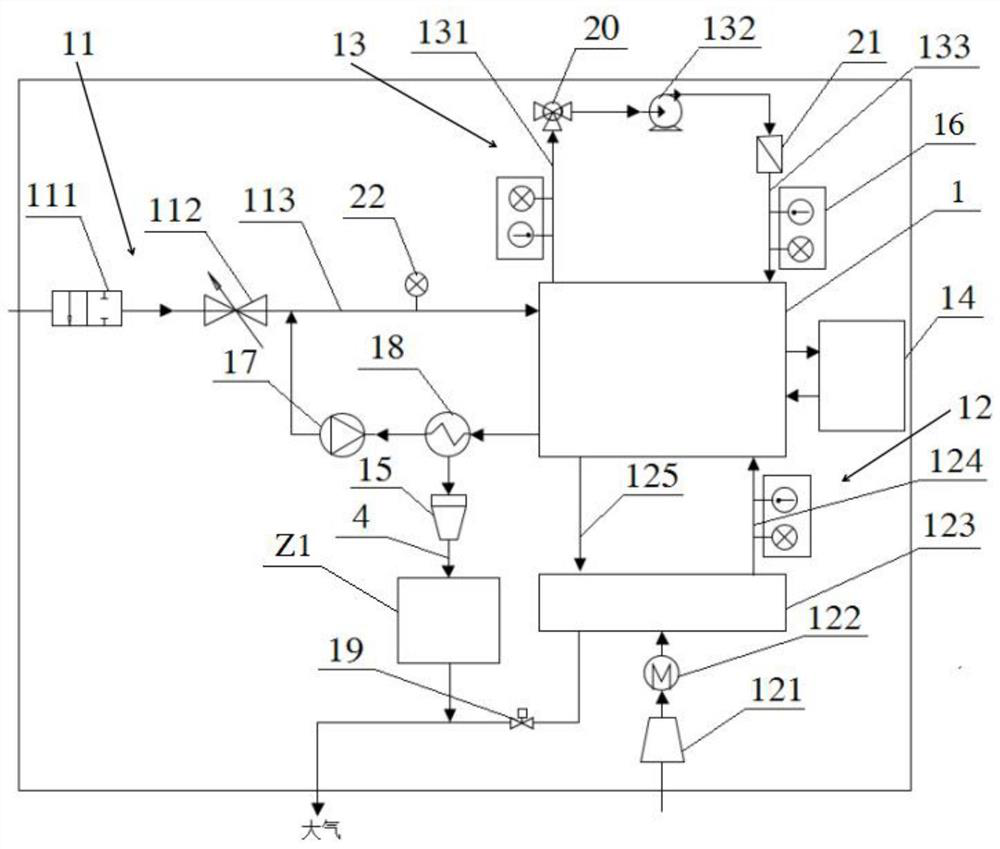
[0043] The exhaust gas treatment device Z1 also includes a fan 10 . The fan 10 is arranged on the side of the second cathode inlet pipe 6 . While the fan 10 is cooling the second fuel cell stack 3, the air can be introduced into the second fuel cell stack 3 through the second cathode air intake pipe 6, so that the cathode air intake circuit of the second fuel cell stack 3 There is no need to set up booster equipment such as air compressor 121, and the cathode air intake mode is equivalent to the air intake mode of a traditional naturally aspirated engine, that is, it can directly inhale atmospheric air at normal pressure. Therefore, more air is blown in by the fan 10 The natural air is used by the second fuel cell stack 3 , that is, sufficient reaction air is provided for the second fuel cell stack 3 .
PUM
 Abstract
Description
Claims
Application Information
 - R&D
- Intellectual Property
- Life Sciences
- Materials
- Tech Scout
- Unparalleled Data Quality
- Higher Quality Content
- 60% Fewer Hallucinations
Browse by: Latest US Patents, China's latest patents, Technical Efficacy Thesaurus, Application Domain, Technology Topic, Popular Technical Reports.
© 2025 PatSnap. All rights reserved.Legal|Privacy policy|Modern Slavery Act Transparency Statement|Sitemap|About US| Contact US: help@patsnap.com