Fault recovery method, computer equipment and storage medium
A technology for fault recovery and fault recovery instructions, applied in neural learning methods, non-redundancy-based fault handling, and generation of response errors, which can solve the problems of poor reliability, low operation efficiency, and high labor costs
- Summary
- Abstract
- Description
- Claims
- Application Information
AI Technical Summary
Problems solved by technology
Method used
Image
Examples
Embodiment 1
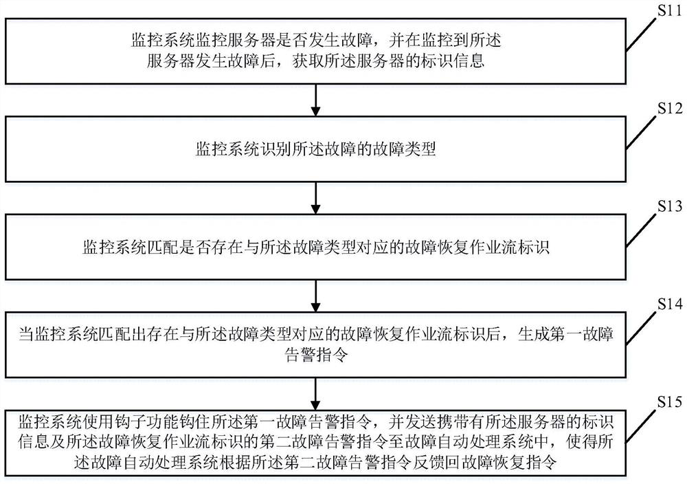
[0052] figure 1 It is a flow chart of the fault recovery method provided by Embodiment 1 of the present invention. The fault recovery method specifically includes the following steps. According to different requirements, the order of the steps in the flow chart can be changed, and some of them can be omitted.
[0053] S11. The monitoring system monitors whether the server fails, and acquires identification information of the server after monitoring that the server fails.
[0054] The fault recovery system includes two subsystems, a monitoring system and an automatic fault processing system. The monitoring system is responsible for monitoring whether a server fails, and obtains the identification information of the faulty server when it detects that the server is faulty.
[0055] The identification information may include: the IP address of the server, the MAC address of the server, and the device identification number of the server.
[0056] The identification information is...
Embodiment 2
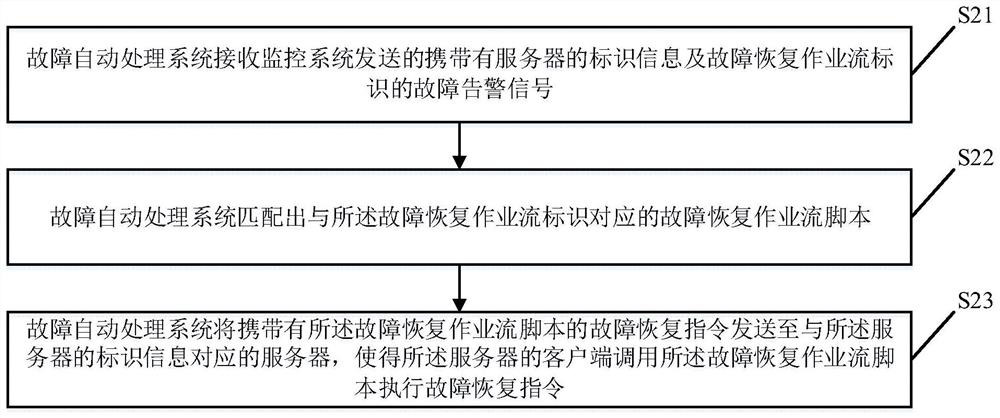
[0097] figure 2 It is a flow chart of the fault recovery method provided by Embodiment 2 of the present invention. The fault recovery method specifically includes the following steps. According to different requirements, the order of the steps in the flow chart can be changed, and some of them can be omitted.
[0098] S21. The automatic fault processing system receives the fault alarm signal sent by the monitoring system and carries the identification information of the server and the identification of the fault recovery workflow.
[0099] S22. The fault automatic processing system matches a fault recovery job flow script corresponding to the fault recovery job flow identifier.
[0100] There are multiple fault recovery job flow scripts pre-developed and configured in the fault automatic processing system, each fault recovery job flow script is used to execute the fault recovery job process of the server, and each fault recovery job flow script has a unique ID as a fault rec...
Embodiment 3
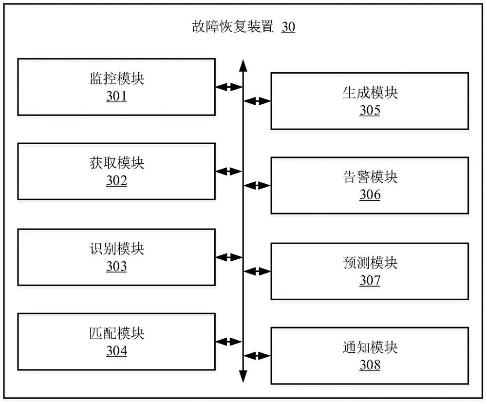
[0113] image 3 It is a structural diagram of the fault recovery device provided by Embodiment 3 of the present invention.
[0114] In some embodiments, the fault recovery device 30 may include a plurality of functional modules composed of program code segments. The program codes of each program segment in the fault recovery device 30 can be stored in the memory of the computer device, and executed by the at least one processor to execute (see for details figure 1 Description) The function of failure recovery.
[0115] In this embodiment, the fault recovery device 30 can be divided into multiple functional modules according to the functions it performs. The functional modules may include: a monitoring module 301 , an acquisition module 302 , an identification module 303 , a matching module 304 , a generation module 305 , an alarm module 306 , a prediction module 307 and a notification module 308 . The module referred to in the present invention refers to a series of compute...
PUM
 Abstract
Description
Claims
Application Information
 - R&D
- Intellectual Property
- Life Sciences
- Materials
- Tech Scout
- Unparalleled Data Quality
- Higher Quality Content
- 60% Fewer Hallucinations
Browse by: Latest US Patents, China's latest patents, Technical Efficacy Thesaurus, Application Domain, Technology Topic, Popular Technical Reports.
© 2025 PatSnap. All rights reserved.Legal|Privacy policy|Modern Slavery Act Transparency Statement|Sitemap|About US| Contact US: help@patsnap.com


