Heat exchange device
A heat exchange device and heat pipe technology, which is applied to heat exchange equipment, indirect heat exchangers, lighting and heating equipment, etc., can solve the problems of low utilization rate, inability to make full use of flue gas energy and high energy in the existing technology, and save energy. consumption, improving energy efficiency, and saving energy
- Summary
- Abstract
- Description
- Claims
- Application Information
AI Technical Summary
Problems solved by technology
Method used
Image

Examples
Embodiment 1
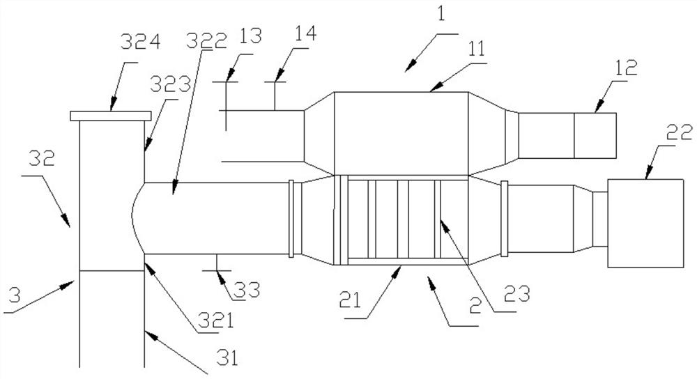
[0036] A heat exchange device, comprising:
[0037] A cold source 1, the cold source 1 includes a first box 11 and a blower 12, and the first box 11 communicates with the blower 12;
[0038] Heat exchanger 2, the heat exchanger 2 includes a second box body 21, a heat pipe 23, an induced draft fan 22, the heat pipe 23 is arranged in the second box body 21, and the induced draft fan 22 is the same as the second box body 21, the second box 21 is connected with the smoke pipe 3;
[0039] The second box 21 is connected to the first box 11, the heat pipe 23 includes a vaporization section and a liquefaction section, and the liquefaction section is arranged between the first box 11 and the second box 21. Junction. The heat pipe 23 is not less than one, and the vaporization section of the heat pipe 23 is distributed in the second box 21 . The flow rate of flue gas in the smoke pipe 3 is 15000~25000Nm 3 / h, the temperature of the flue gas is 350~450°C. The flow rate of the air in ...
Embodiment 2
[0043] A heat exchange device, comprising:
[0044] A cold source 1, the cold source 1 includes a first box 11 and a blower 12, and the first box 11 communicates with the blower 12;
[0045] Heat exchanger 2, the heat exchanger 2 includes a second box body 21, a heat pipe 23, an induced draft fan 22, the heat pipe 23 is arranged in the second box body 21, and the induced draft fan 22 is the same as the second box body 21, the second box 21 is connected with the smoke pipe 3;
[0046] The second box 21 is connected to the first box 11 , the heat pipe 23 includes a vaporization section and a liquefaction section, and the vaporization section is distributed in the second box 21 . The heat pipe 23 is not less than one, and the liquefied section of the heat pipe 23 passes through the walls of the first box 11 and the second box 12 and enters the first box 11 . The flow rate of flue gas in the smoke pipe 3 is 15000~25000Nm 3 / h, the temperature of the flue gas is 350~450°C. The ...
Embodiment 3
[0049]The difference between embodiment 3 and embodiment 1 is that the heat pipe is coated with a self-cleaning coating, and the self-cleaning coating is formed by coating the heat pipe with a self-cleaning coating; the preparation method of the self-cleaning coating is as follows: :
[0050] Get 22Kg of polytetrafluoroethylene resin, 6Kg of polyether sulfone resin, 7 parts of modified nano-silica, 6Kg of modified nano-titanium dioxide, 0.6Kg of dispersant, 0.7Kg of defoamer, 0.7Kg of leveling agent, and 110Kg of xylene ;
[0051] Add polyethersulfone resin into xylene, heat and stir to dissolve evenly, add modified nano-silica, modified nano-titanium dioxide, defoamer, leveling agent, dispersant, and ball mill in a ball mill for 36 hours, and the slurry obtained by ball milling Stir and mix the material with polytetrafluoroethylene resin powder evenly, and sieve to obtain the self-cleaning coating.
[0052] The preparation method of the modified nano-silica is as follows: m...
PUM
| Property | Measurement | Unit |
|---|---|---|
| porosity | aaaaa | aaaaa |
Abstract
Description
Claims
Application Information
 - Generate Ideas
- Intellectual Property
- Life Sciences
- Materials
- Tech Scout
- Unparalleled Data Quality
- Higher Quality Content
- 60% Fewer Hallucinations
Browse by: Latest US Patents, China's latest patents, Technical Efficacy Thesaurus, Application Domain, Technology Topic, Popular Technical Reports.
© 2025 PatSnap. All rights reserved.Legal|Privacy policy|Modern Slavery Act Transparency Statement|Sitemap|About US| Contact US: help@patsnap.com