An intelligent optical cable monitoring method, device, computer equipment and storage medium
A computer program and optical cable technology, applied in electrical components, electromagnetic wave transmission systems, transmission systems, etc., can solve the problems of long time consumption and untimely maintenance of optical cables, so as to reduce the impact of faults and improve maintenance efficiency.
- Summary
- Abstract
- Description
- Claims
- Application Information
AI Technical Summary
Problems solved by technology
Method used
Image

Examples
Embodiment 1
[0047] The present invention provides an intelligent optical cable monitoring method, which can be applied to different computer devices, including but not limited to various personal computers, notebook computers, smart phones and tablet computers.
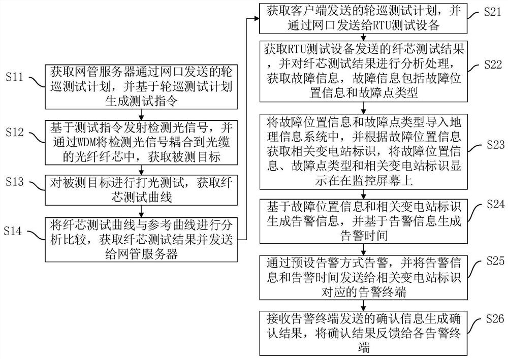
[0048] Such as figure 1 As shown, the present invention provides a kind of intelligent optical cable monitoring method, comprises the following steps that RTU testing equipment is carried out:
[0049]S11: Obtain the polling test plan sent by the network management server through the network port, and generate a test instruction based on the polling test plan.
[0050] Wherein, the patrol test plan refers to the plan set by the user for the patrol test of the optical fiber core in the optical cable, including but not limited to the patrol time and test content of the patrol test. By formulating the patrol test plan, the optical cable can be tested according to a certain patrol time, so as to avoid the long maintenance time cause...
Embodiment 2
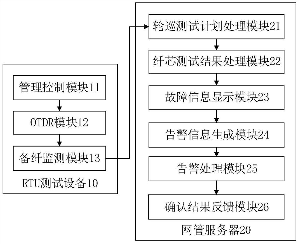
[0085] Such as image 3 As shown, the difference between this embodiment and Embodiment 1 is that an intelligent optical cable monitoring device includes an RTU testing device 10 and a network management server 20 .
[0086]The RTU test equipment 10 includes a management control module 11 , an OTDR module 12 and a fiber backup monitoring module 13 .
[0087] The management control module 11 is used to obtain the polling test plan sent by the network management server through the network port, and generate test instructions based on the polling test plan.
[0088] The OTDR module 12 is configured to emit a detection optical signal based on a test instruction, and couple the detection optical signal into the fiber core of the optical cable through WDM to acquire the target under test.
[0089] The fiber preparation monitoring module 13 is used to perform a lighting test on the target to be tested, obtain a fiber core test curve and send it to the network management server.
[...
Embodiment 3
[0104] This embodiment provides a computer device, which may be a server, and its internal structure diagram may be as follows Figure 4 shown. The computer device includes a processor, memory, network interface and database connected by a system bus. Wherein, the processor of the computer device is used to provide calculation and control capabilities. The memory of the computer device includes a computer-readable storage medium and an internal memory. The computer readable storage medium stores an operating system, computer programs and databases. The internal memory provides an environment for the operation of the operating system and computer programs in the computer-readable storage medium. The database of the computer equipment is used to store the data involved in the intelligent optical cable monitoring method. The network interface of the computer device is used to communicate with an external terminal via a network connection. When the computer program is execute...
PUM
 Abstract
Description
Claims
Application Information
 - R&D
- Intellectual Property
- Life Sciences
- Materials
- Tech Scout
- Unparalleled Data Quality
- Higher Quality Content
- 60% Fewer Hallucinations
Browse by: Latest US Patents, China's latest patents, Technical Efficacy Thesaurus, Application Domain, Technology Topic, Popular Technical Reports.
© 2025 PatSnap. All rights reserved.Legal|Privacy policy|Modern Slavery Act Transparency Statement|Sitemap|About US| Contact US: help@patsnap.com