A charging system, device and charging control method

A technology for charging systems and power supply equipment, applied in battery circuit devices, current collectors, electric vehicles, etc., can solve the problems of charging speed, reduced charging energy efficiency, uncontrollable and uncontrollable charging current, etc., to improve user experience, charging The effect of increased frequency and low charging power consumption

Active Publication Date: 2022-02-11
ZHUHAI JIELI TECH
View PDF8 Cites 0 Cited by
  • Summary
  • Abstract
  • Description
  • Claims
  • Application Information

AI Technical Summary

Problems solved by technology

Moreover, the shunting of other functional units on the earphone end is often an uncontrollable and unpredictable sudden event, making it impossible for the charging box end to prepare for flow control in advance.
[0006] It can be seen that there is an uncontrollable shunt of the input charging current in the functional unit of the earphone end, which leads to a decrease in the current injected into the rechargeable battery and a decrease in the current injected into the rechargeable battery. , Expected constant current charging, resulting in reduced charging speed and charging energy efficiency

Method used


Image

  • A charging system, device and charging control method
  • A charging system, device and charging control method
  • A charging system, device and charging control method

Examples


Embodiment Construction

[0059] Now in conjunction with the accompanying drawings, the preferred embodiments of the present invention will be described in detail.

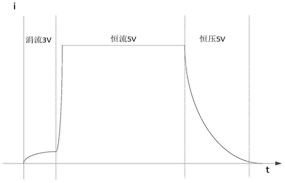
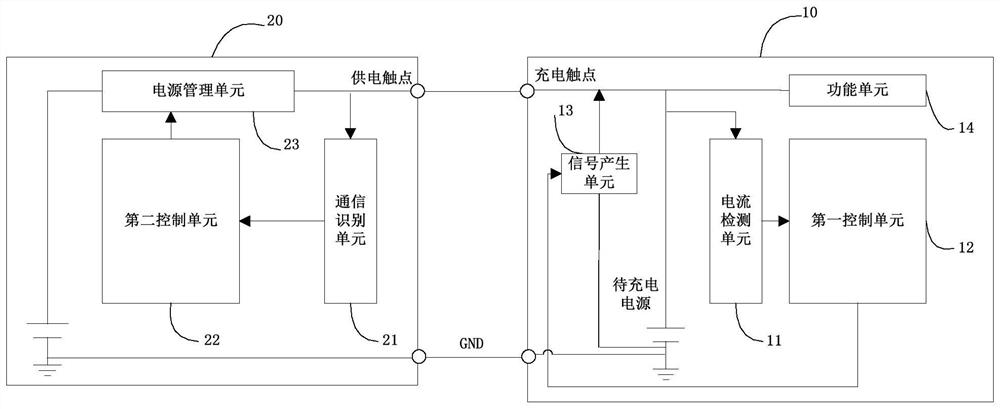
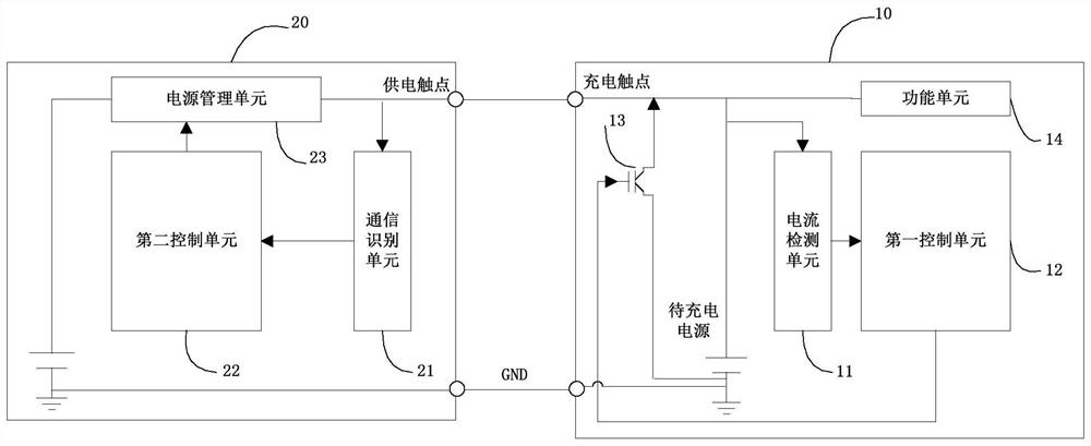
[0060] figure 2 It is a schematic diagram of an embodiment of the charging system composed of the power supply equipment 20 and the equipment to be charged 10 in the present invention. The system monitors the charging current flowing into the power supply to be charged in real time, and feeds back to the power supply equipment 20 in a simple manner, and adjusts the power supply equipment 20 in real time. The output power supply voltage is communicated with the device to be charged 10 through the power supply device 20, so that when the injected current of the device to be charged 10 does not meet the preset range value, it is fed back to the power supply device 20, and the power supply device 20 dynamically adjusts the charging voltage. This enables the power supply device 20 to realize refined constant current charging during the chargin...


PUM


Abstract

The charging system of the present invention includes the equipment to be charged and the power supply equipment. In the constant current charging stage, the current detection unit detects the current value of the current flowing into the power supply to be charged; when the current current value deviates from the predetermined current range, the current detection unit outputs a current deviation signal, The first control unit generates a control signal according to the deviation direction and degree of deviation of the current deviation signal, and the control signal generation unit generates a rectangular wave signal with a predetermined number of cycles and a predetermined duty cycle; the communication identification unit detects the rectangular wave signal through the power supply contact and outputs To the second control unit, the second control unit generates a power supply control signal according to the cycle number and duty ratio of the rectangular wave signal, controls the power management unit to change the supply voltage at the output terminal, and changes the current value flowing into the power supply to be charged toward a predetermined current range. It enables the power supply equipment to realize refined constant current charging in the process of charging the equipment to be charged, so that it can always maintain better charging timeliness and lower charging energy consumption.

Description

technical field [0001] The invention relates to the technical field of charging management, in particular to a charging system, equipment and charging control method capable of realizing refined constant current charging. Background technique [0002] With the use of TWS (True Wireless Stereo, true wireless stereo) wireless devices, users' demand for wireless devices is also increasing, for example, TWS earphones and the like. At this stage, the TWS wireless device is powered by a built-in battery. When the power consumption of the device reaches a certain level (for example, below 10%), it will prompt that it needs to be charged. The user connects the TWS wireless device to the supporting charging device to charge until full. [0003] At present, for example, TWS wireless earphones are charged. TWS earphones are usually placed in the matching earphone charging box, which is basically the same as the charging process of other rechargeable batteries at this stage, such as f...

Claims


Application Information

Patent Timeline
Patent Type & Authority Patents(China)
IPC IPC(8): H02J7/00
CPCH02J7/00714
Inventor 桑耀黄海涛许飞
Owner ZHUHAI JIELI TECH
Why Eureka
Try Eureka