Electronic package and carrier substrate and manufacturing method thereof

An electronic package and carrier substrate technology, which is applied in the manufacture of electrical components, electrical solid-state devices, semiconductor/solid-state devices, etc. The effect of increasing the wiring area and low production cost

Active Publication Date: 2020-11-03
SILICONWARE PRECISION IND CO LTD
View PDF4 Cites 0 Cited by
  • Summary
  • Abstract
  • Description
  • Claims
  • Application Information

AI Technical Summary

Problems solved by technology

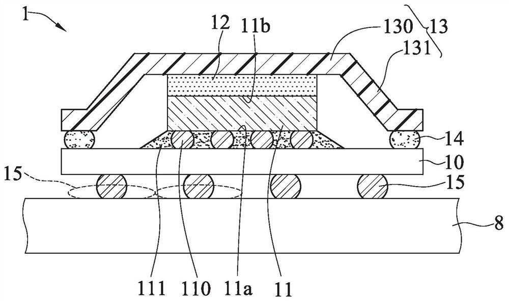
[0007] However, in the existing semiconductor package 1, there is a need for a large-sized package substrate 10, such as a board size of 100*100mm 2 It is not yet mass-producible, and the production cost of a single board is extremely high, so it is not competitive in the market

Method used


Image

  • Electronic package and carrier substrate and manufacturing method thereof
  • Electronic package and carrier substrate and manufacturing method thereof
  • Electronic package and carrier substrate and manufacturing method thereof

Examples


Embodiment Construction

[0057] Embodiments of the present invention are described below through specific examples, and those skilled in the art can easily understand other advantages and effects of the present invention from the content disclosed in this specification.

[0058]It should be noted that the structures, proportions, sizes, etc. shown in the drawings attached to this specification are only used to match the content disclosed in the specification for the understanding and reading of those skilled in the art, and are not intended to limit the implementation of the present invention. Limiting conditions, so there is no technical substantive meaning, any modification of structure, change of proportional relationship or adjustment of size, without affecting the effect and purpose of the present invention, should still fall within the scope of the present invention. The disclosed technical content must be within the scope covered. At the same time, terms such as "above", "first", "second" and "...


PUM


Abstract

The invention relates to an electronic package and a carrier substrate and a manufacturing method thereof, the electronic package comprising the steps of arranging at least one circuit member on a first circuit structure, forming a coating layer on the first circuit structure to coat the circuit member, forming a second circuit structure on the coating layer, and electrically connecting the secondcircuit structure with the circuit member; therefore, the circuit component is embedded in the coating layer through the existing packaging process to increase the wiring area, so that for the requirement of the packaging substrate with a large-size plate surface, the mass production is realized, and the process cost is low.

Description

technical field [0001] The invention relates to a package structure, especially to an electronic package, its carrier substrate and its manufacturing method. Background technique [0002] With the improvement of the function and processing speed of electronic products, semiconductor chips, which are the core components of electronic products, need to have higher density circuit components (Electronic Components) and electronic circuits (Electronic Circuits). It produces a large amount of heat energy. In addition, the encapsulation compound covering the semiconductor chip is a poor heat transfer material with a thermal conductivity of only 0.8Wm-1k-1 (that is, the heat dissipation efficiency is not good), so if it cannot be effectively dissipated The heat generated will cause damage to semiconductor chips or cause product reliability problems. [0003] In order to quickly dissipate heat energy into the atmosphere, the industry usually configures a heat sink (Heat Sink or Hea...

Claims


Application Information

Patent Timeline
Patent Type & Authority Applications(China)
IPC IPC(8): H01L23/498H01L21/48
CPCH01L23/49822H01L23/49827H01L21/4857H01L21/486H01L23/49838H01L23/145H01L23/49816H01L23/5385H01L23/49811H01L23/3675H01L23/42H01L23/5383H01L2224/32225H01L2224/16227H01L2224/73204H01L2224/73253H01L2924/15311H01L2924/16251H01L25/0655H01L2224/97H01L2224/92225H01L2224/92125H01L2224/32245H01L2224/04026H01L2224/05644H01L24/16H01L2224/16237H01L2224/131H01L2224/83H01L2224/81H01L2924/00014H01L2224/16225H01L2924/00H01L2924/014H01L25/0657H01L23/3114H01L23/5226H01L2225/06541H01L21/563H01L21/4882H01L24/13
Inventor 何祈庆马伯豪薛宇廷曾景鸿陆冠华张宏达
Owner SILICONWARE PRECISION IND CO LTD
Why Eureka
Try Eureka