
Energy dissipation box

An energy dissipation box and energy dissipation technology, applied in water conservancy projects, marine engineering, coastline protection and other directions, can solve the problems of large negative pressure and poor adaptability, and can increase the flow area, increase friction, and increase the degree of energy dissipation. Effect

Active Publication Date: 2020-11-03
HOHAI UNIV
View PDF5 Cites 0 Cited by
  • Summary
  • Abstract
  • Description
  • Claims
  • Application Information

AI Technical Summary

Problems solved by technology

[0004] Purpose of the invention: In order to overcome the defects of the prior art, the present invention provides an energy dissipation box, which can overcome the shortcomings of excessive negative pressure and poor adaptability during the energy dissipation process, and realize self-adaptive energy dissipation

Method used


Image

  • Energy dissipation box
  • Energy dissipation box
  • Energy dissipation box

Examples


Embodiment Construction

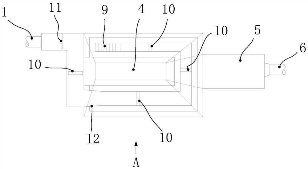
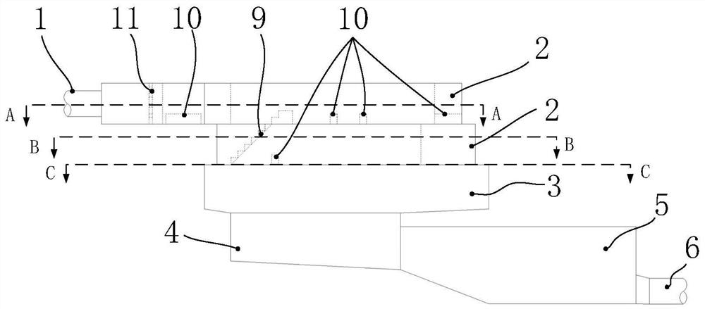
[0022] Such as Figure 1-2 As shown, the energy dissipation box of this embodiment is an adaptive energy dissipation box with a circular layered structure. Including water inlet 1, energy dissipation flow path 2, storage flow stratosphere 3, sink 4, water storage tank 5 and water outlet 6. Wherein, the energy dissipating flow paths 2 are respectively the first energy dissipating flow path 21 and the second energy dissipating flow path 22, and the first energy dissipating flow path 21 and the second energy dissipating flow path 22 are stacked sequentially from top to bottom.

[0023] Specifically, please refer to image 3 As shown, the flow channel of the first energy dissipation flow channel 21 includes the first top flow channel 201, the second top flow channel 202, the third top flow channel 203, the fourth top flow channel 204 and the fifth top flow channel which are vertically connected in sequence. Road 205. The bottom surface of the energy dissipation channel 2 is flu...


PUM


Abstract

The invention discloses an energy dissipation box, and belongs to the technical field of water conservancy and hydropower engineering equipment. The energy dissipation box dissipates energy in a layered mode, all layers dissipate energy in a dispersed mode, and the problem that a box body bears too large pressure during energy dissipation can be solved. Energy dissipation holes, grid bars and energy dissipation ridges are arranged in all the flow channels, so that the energy dissipation strength is improved, and besides, self-adaptive energy dissipation can be achieved for water flow of different flow speeds. In addition, the open design of a flow storage stratospheric layer can solve the exhaust problem during energy dissipation. Due to the layered structure and the design that the extending directions of every two adjacent flow channels are different, the flowing area of water flow is effectively enlarged, friction between the water flow and the box body is increased, and the energydissipation effect is more remarkable.

Description

technical field [0001] The invention relates to water conservancy and hydropower engineering equipment, in particular to an energy dissipation box used in water conservancy and hydropower engineering. Background technique [0002] In recent years, in order to effectively solve the problem of uneven temporal and spatial distribution of water resources and allocate water resources more rationally, a large number of water conservancy projects have emerged. In these water conservancy projects, usually all are to pressurize the water body by means of a pressurized water pump to make it reach the destination. But in many cases, the high-speed water flow also carries huge energy when it reaches the destination. In order to protect the lower reservoir buildings, the excess energy must be eliminated before the water body reaches the lower reservoir. The idea of ​​energy dissipation is to spread the kinetic energy of high-speed water quickly and safely, so that it can flow smoothly t...

Claims


Application Information

Patent Timeline
Patent Type & Authority Applications(China)
IPC IPC(8): E02B8/06
CPCE02B8/06
Inventor 刘芳俞晓东张健陈胜倪尉祥蒋捷
Owner HOHAI UNIV
Learn More