Die cutting method of gauze film layer

A mesh and die-cutting technology, which is applied in metal processing and other directions, can solve the problems of inaccurate manual lamination accuracy, low yield, and difficulty in discharging punching waste, so as to save manual assembly work, ensure lamination accuracy, The effect of increasing productivity

Active Publication Date: 2020-11-03
苏州佰瑞兴实业有限公司
View PDF10 Cites 2 Cited by
  • Summary
  • Abstract
  • Description
  • Claims
  • Application Information

AI Technical Summary

Problems solved by technology

The first method has the problem of inaccurate manual lamination accuracy and low production capacity, and the second method has the technical problem of being difficult to discharge punching waste, resulting in low yield defects

Method used


Image

  • Die cutting method of gauze film layer
  • Die cutting method of gauze film layer
  • Die cutting method of gauze film layer

Examples


Embodiment 1

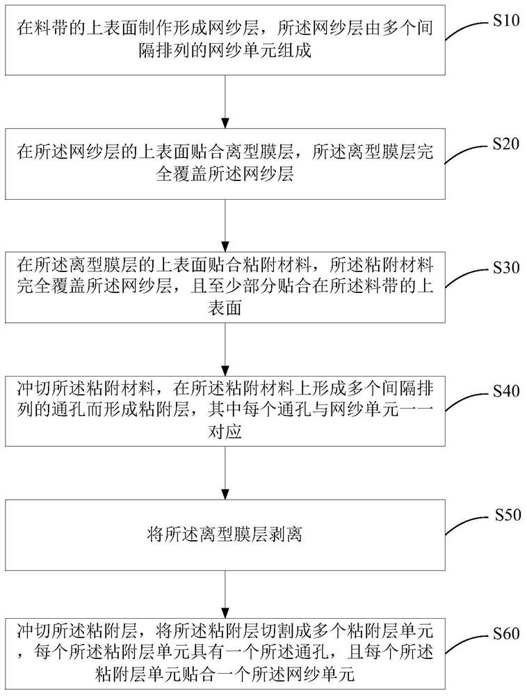
[0034] Such as figure 1 Shown, the die-cutting method of the gauze film layer of the present application comprises the steps:

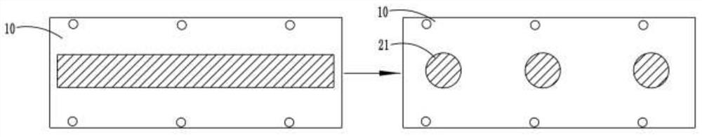
[0035] Step S10 : Fabricate and form a mesh layer 20 on the upper surface of the material tape 10 , the mesh layer 20 is composed of a plurality of mesh units 21 arranged at intervals.

[0036] Specifically, step S10 is: as Figure 2A As shown, the material tape 10 is used as a carrier medium. After the mesh material is attached to the material tape 10 , the mesh material is punched into a plurality of mesh units 21 by a die-cutting device to form the mesh layer 20 . The shape of the mesh unit 21 may be circular, square, triangular, etc., which is not limited.
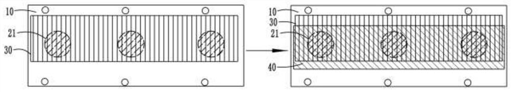
[0037] Step S20 : ​​Attach a release film layer 30 on the upper surface of the mesh layer 20 , and the release film layer 30 completely covers the mesh layer 20 .

[0038] Step S30 : Paste an adhesive material on the upper surface of the release film layer 30 , the adhesive material complet...

Embodiment 2

[0049]The die-cutting equipment that present embodiment 2 provides comprises three parts, is sticking device, punching device and stripping device respectively, and sticking device is used for sticking gauze material, release film layer, adhesive material, and punching device is used. For die-cutting the mesh material and the adhesive material, the peeling device is used for peeling off the release film layer. Wherein, after the attaching device attaches the mesh material on the material tape 10, the punching device punches the mesh material to form the mesh layer 20; Attach the release film layer 30 and the adhesive layer 40 in sequence; when the attachment device attaches the adhesive layer 40 to the release film layer 30, the punching device punches the adhesive layer 40, and then the peeling device peels off the release film. Film layer 30 ; after the peeling device peels off the release film layer 30 , the die-cutting device die-cuts the adhesive layer 40 into a plurality...


PUM


Abstract

The invention discloses a die cutting method of a gauze film layer. The die cutting method comprises the steps that a gauze layer is manufactured and formed on the upper surface of a material belt, wherein the gauze layer is composed of a plurality of gauze units arranged at intervals; a release film layer is attached to the upper surface of the gauze layer, wherein the release film layer completely covers the gauze layer; an adhesive material is attached to the upper surface of the release film layer, wherein the adhesive material completely covers the gauze layer, and is at least partially attached to the upper surface of the material belt; and the adhesive material is punched, a plurality of through holes which are arranged at intervals are formed in the adhesive material to form an adhesive layer, each through hole is in one-to-one correspondence with the gauze unit. The release film layer is attached to the gauze layer, so that the gauze layer is prevented from being damaged whenthe adhesive material is punched, meanwhile, a punching material of the adhesive layer can be discharged easily, a finished product is directly subjected to die cutting, the attaching precision is guaranteed, manual assembling operation is omitted, and the productivity is greatly improved. Finally, the release film layer is stripped in the side direction so as to realize lamination of the adhesivelayer and the gauze units.

Description

technical field [0001] The invention belongs to the technical field of mesh cutting, and in particular relates to a method for die-cutting a mesh film layer. Background technique [0002] When making the mesh structure in the prior art, there are generally two different methods. One method is to die-cut the mesh layer and the double-sided adhesive layer respectively, and then combine the mesh layer after die-cutting with the tape after die-cutting. The double-sided adhesive layer of the hole is pasted manually to assemble the finished product; another method is to directly attach the double-sided adhesive layer on the die-cut mesh layer, and then die-cut and punch the double-sided adhesive layer to remove the punching. Hole scrap to get finished product. The first method has the problem of inaccurate manual lamination accuracy and low production capacity, and the second method has the technical problem of being difficult to discharge punching waste, resulting in the defect ...

Claims


Application Information

Patent Timeline
Patent Type & Authority Applications(China)
IPC IPC(8): B26F1/38B26F1/44
CPCB26F1/38B26F1/44
Inventor 王磊李志华石永锋
Owner 苏州佰瑞兴实业有限公司
Why Eureka
Try Eureka