Film slitting machine
A slitting machine and film technology, applied in metal processing and other directions, can solve problems such as uneven cutting surface
- Summary
- Abstract
- Description
- Claims
- Application Information
AI Technical Summary
Problems solved by technology
Method used
Image
Examples
Embodiment 1
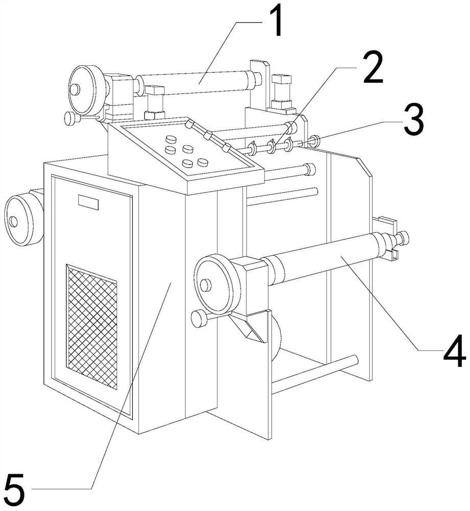
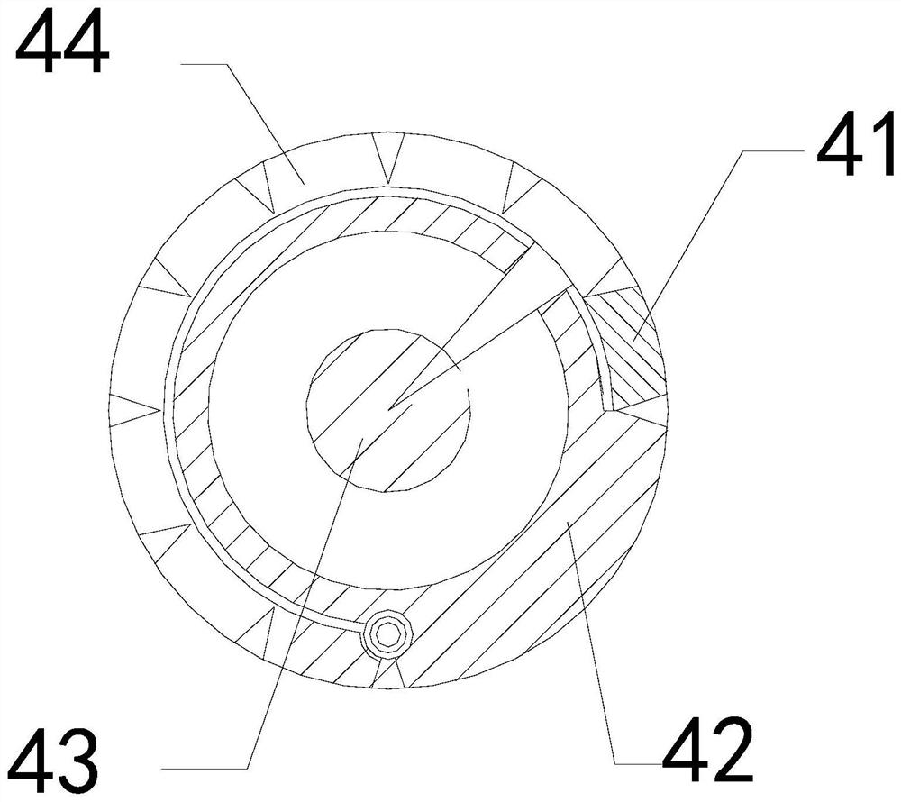
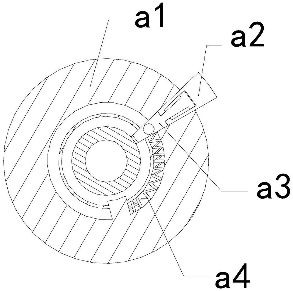
[0026] For example figure 1 -example Figure 5 Shown:
[0027] The invention provides a film slitting machine, the structure of which includes a pulling roller 1, a slitting knife 2, a slitting frame 3, a feeding roller 4, and a body 5, the pulling roller 1 is connected with the body 5, and the The slitting knife 2 and the slitting frame 3 are an integrated structure, the slitting frame 3 is welded to the body 5, and the feeding roller 4 is engaged with the body 5; the feeding roller 4 includes a clamping block 41 , the guide frame 42, the inner frame 43, the extension surface 44, the clamping block 41 and the extension surface 44 are integral structures, the inner frame 43 is installed in the inner position of the guide frame 42, the extension surface 44 and the guide frame 42 hinge connections.
[0028] Wherein, the inner frame 43 includes a receiving plate a1, a protruding block a2, a guide rod a3, and an elastic bar a4, the protruding block a2 is in clearance fit with t...
Embodiment 2
[0034] For example Figure 6 -example Figure 8 Shown:
[0035] Wherein, the slitting knife 2 includes a cutter body c1, a linkage rod c2, a linkage rod c2, a rebound piece c3, a sleeve frame c4, and a solid ring c5. The cutter body c1 is embedded and connected with the linkage rod c2, and the linkage The rod c2 is engaged with the middle solid ring c5, and the rebound piece c3 is installed between the linkage rod c2 and the sleeve frame c4. Strong spring steel material, through the thrust of the film on the cutter body c1, the linkage rod c2 can drive the cutter body c1 to swing backward along the middle solid ring c5, and the linkage rod c2 can be pulled and reset by the rebound piece c3.
[0036]Wherein, the cutter body c1 includes a blade c11, a connecting rod c12, a blade face c13, and an elastic piece c14. The blade c11 is movably engaged with the blade face c13 through the connecting rod c12. Between the knife face c13, there are three connecting rods c12, which are ...
PUM
 Abstract
Description
Claims
Application Information
 - R&D
- Intellectual Property
- Life Sciences
- Materials
- Tech Scout
- Unparalleled Data Quality
- Higher Quality Content
- 60% Fewer Hallucinations
Browse by: Latest US Patents, China's latest patents, Technical Efficacy Thesaurus, Application Domain, Technology Topic, Popular Technical Reports.
© 2025 PatSnap. All rights reserved.Legal|Privacy policy|Modern Slavery Act Transparency Statement|Sitemap|About US| Contact US: help@patsnap.com


