
A kind of miniature optical fiber coupled optoelectronic device and its assembly method

A technology of optical fiber coupling and optoelectronic devices, which is applied in the field of miniature optical fiber coupled optoelectronic devices and their installation and adjustment, can solve the problems of difficulty in fixing optical fiber components, bending of optical fiber components and electrical devices, and lack of angle adjustment, so as to achieve uniform force, The effect of avoiding and avoiding bending safely

Active Publication Date: 2022-03-15
深圳新海讯光电有限公司
View PDF13 Cites 0 Cited by
  • Summary
  • Abstract
  • Description
  • Claims
  • Application Information

AI Technical Summary

Problems solved by technology

[0003] At present, most fiber coupling adjustments are X / Y / Z three-dimensional adjustments, without angle adjustment. Even if the angle adjustment can be realized through an external adjustment bracket, it will make it difficult to fix the fiber optic components. For this reason, the Chinese patent discloses A miniature fiber-coupled optoelectronic device and its assembly method (patent number: CN104280842B), including a tube shell and a cover plate, a heat sink, a light-emitting chip, a shell connector, a spherical adjustment piece and a metal optical fiber assembly. The technical solution is suitable for optical fiber coupling of optoelectronic devices such as semiconductor lasers or solid-state lasers, and has the advantages of simple structure, convenient installation and operation, and long-term reliability.
[0004] However, whether it is the above-mentioned disclosed technical solution or the traditional technical solution, when adjusting, it will affect the optical fiber components connected and installed on it, that is, after the angle change or position change is completed, the position and position of the optical fiber components will also be affected. Changes will occur accordingly, so that in normal use, slight changes in position will be caused by the gravity of the fiber optic component itself, and it may also cause bending between the fiber optic component and the electrical device, regardless of the adjusted position. Or the safety of optical fiber components is affected to a certain extent. Therefore, how to change or control the impact of the above problems on electrical devices and optical fiber components is a major problem that is currently faced and needs to be solved.

Method used


Image

  • A kind of miniature optical fiber coupled optoelectronic device and its assembly method
  • A kind of miniature optical fiber coupled optoelectronic device and its assembly method
  • A kind of miniature optical fiber coupled optoelectronic device and its assembly method

Examples


Embodiment Construction

[0025] The technical solution of this patent will be further described in detail below in conjunction with specific embodiments.

[0026] Embodiments of the present patent are described in detail below, examples of which are shown in the drawings, wherein the same or similar reference numerals designate the same or similar elements or elements having the same or similar functions throughout. The embodiments described below by referring to the figures are exemplary and are only used for explaining the patent, and should not be construed as limiting the patent.

[0027] In the description of this patent, it is to be understood that the terms "center", "upper", "lower", "front", "rear", "left", "right", "vertical", "horizontal", The orientation or positional relationship indicated by "top", "bottom", "inner", "outer", etc. is based on the orientation or positional relationship shown in the drawings, and is only for the convenience of describing this patent and simplifying the des...


PUM


Abstract

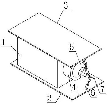
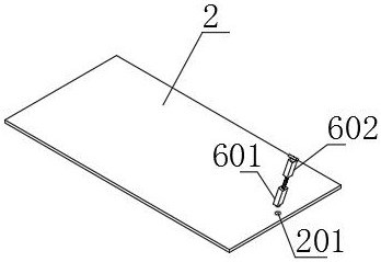
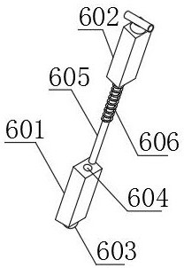
The invention discloses a miniature optical fiber coupled optoelectronic device and an assembly method thereof, comprising a shell, a base plate, a top plate, a connector, a rotating ball, a horizontal holding mechanism and a metal optical fiber assembly, the top of the base plate and the bottom of the shell are fixed by bolts Connection, the bottom of the top plate is fixedly connected with the top of the shell by bolts, the connecting piece is installed in the middle of the right side of the shell by bolts, the rotating ball is embedded in the inner cavity of the connecting piece, and the horizontal holding mechanism is set on the top of the base plate As well as the bottom of the top plate, the metal optical fiber assembly is installed through the inner cavity of the rotating ball. The function of the horizontal holding mechanism in the entire electrical device is reflected in two aspects of normal use and adjustment use. The irregular rotation adjustment is still along the XYZ axis. Sequence adjustment, all through the use of weighing columns, support columns and limit sleeves, to ensure that the optical fiber components are in and maintained in a horizontal state, and at the same time, the force is uniform, and the position will not be shifted due to gravity when the position is adjusted.

Description

technical field [0001] The invention relates to the technical field of optical fiber coupled optoelectronic devices, in particular to a miniature optical fiber coupled optoelectronic device and an assembly method thereof. Background technique [0002] Fiber-coupled optoelectronic devices are widely used in laser communication, fiber laser pumping, material processing and processing, etc. At present, fiber-coupled optoelectronic devices require very accurate positioning of the light-emitting chip, so that fiber coupling can have high coupling efficiency. [0003] At present, most fiber coupling adjustments are X / Y / Z three-dimensional adjustments, without angle adjustment. Even if the angle adjustment can be realized through an external adjustment bracket, it will make it difficult to fix the fiber optic components. For this reason, the Chinese patent discloses A miniature fiber-coupled optoelectronic device and its assembly method (patent number: CN104280842B), including a tu...

Claims


Application Information

Patent Timeline
Patent Type & Authority Patents(China)
IPC IPC(8): G02B6/42
CPCG02B6/422
Inventor 吴海平肖庆强
Owner 深圳新海讯光电有限公司
Learn More