
Wireless fire extinguishing system for energy storage station and control method thereof

A fire-fighting system and energy storage station technology, applied in fire alarms, instruments, fire rescue, etc., can solve problems such as high maintenance requirements, battery combustion chain reaction, thermal runaway energy storage system safety, etc., to save cables and Construction cost, effect of optimized system operation control method

Inactive Publication Date: 2020-11-03
NR ELECTRIC CO LTD +1
View PDF5 Cites 8 Cited by
  • Summary
  • Abstract
  • Description
  • Claims
  • Application Information

AI Technical Summary

Problems solved by technology

Once a safety problem occurs, it often causes a chain reaction of battery combustion, leading to a loss of control and heavy losses
[0004] 2) In the battery energy storage system, the voltage of the battery pack is generally above 700V, and the high-voltage DC system puts forward extremely high requirements for system insulation and protection; All may cause insulation drop, resulting in electric leakage, sparking, and cable contact resistance increase heating, etc., causing safety accidents
[0005] 3) In the grid-side battery energy storage system, the complex system often produces a harsh electromagnetic environment, which leads to false alarms and malfunctions of the system, and unpredictable safety accidents
[0006] 4) Battery overcharge, overdischarge, overcurrent, overtemperature, short circuit, thermal runaway, etc. are the biggest safety hazards of the energy storage system
[0013] The energy storage system has high cost, low reliability, complex or difficult maintenance, high maintenance requirements, and high requirements for operation and maintenance management personnel
[0014] The existing fire alarm system collects and controls the signals of the fire extinguishing equipment through the modules based on the industrial control platform. The communication method still adopts the industrial bus, the transmission efficiency is low, and the field wiring is complicated.

Method used


Image

  • Wireless fire extinguishing system for energy storage station and control method thereof
  • Wireless fire extinguishing system for energy storage station and control method thereof
  • Wireless fire extinguishing system for energy storage station and control method thereof

Examples


Embodiment Construction

[0046] The specific implementation manners of the present application will be described in more detail below with reference to the drawings and embodiments, so as to better understand the solutions of the present application and the advantages of various aspects. However, the specific embodiments and examples described below are for the purpose of illustration only, rather than limiting the application.

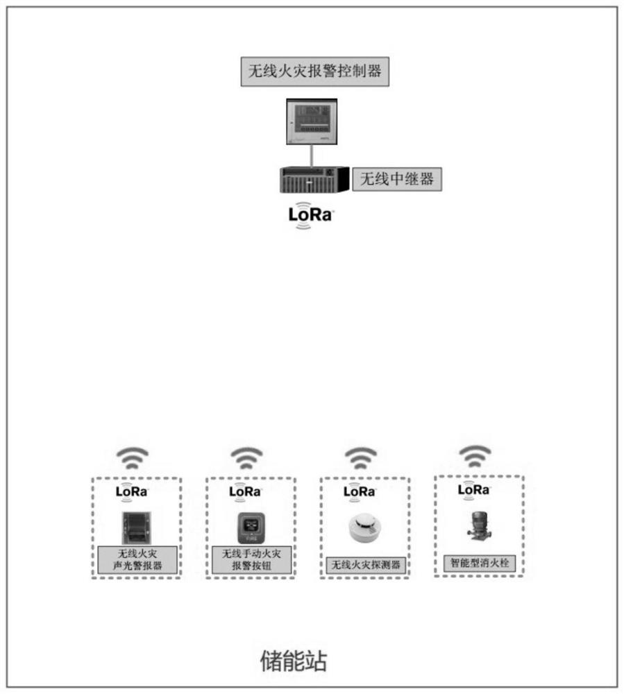
[0047] like figure 1 As shown, this embodiment configures a set of centralized linkage fire protection system based on LoRa wireless communication technology, including:

[0048] Wireless detectors, covering the entire energy storage station, are used to collect environmental information of the energy storage station in real time;

[0049] A wireless repeater, configured to receive the environmental information collected by the wireless detector;

[0050] Wireless sound and light siren, used to send out alarm signal;

[0051] An automatic fire extinguishing system, which i...


PUM


Abstract

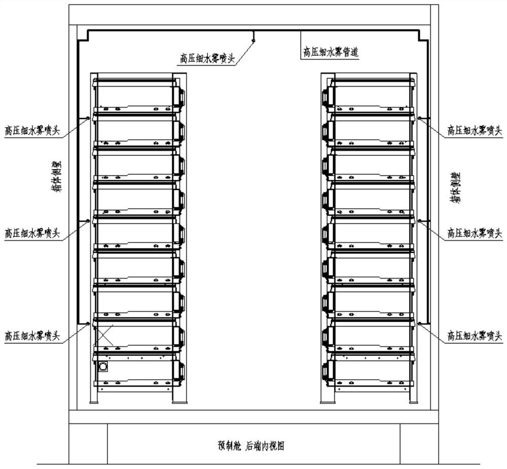
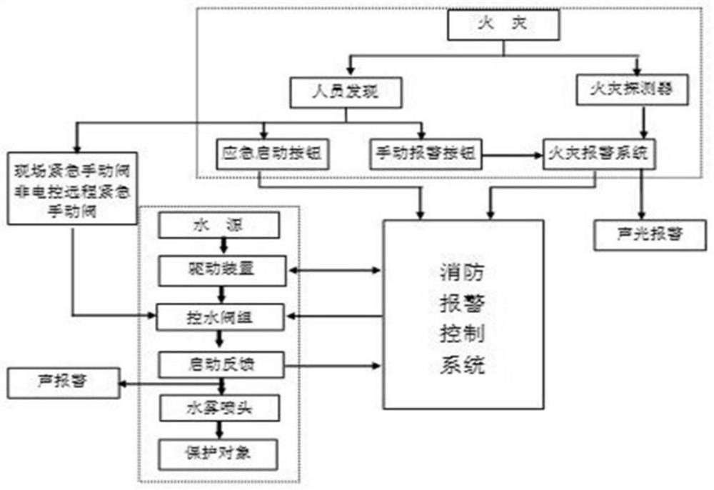
The invention discloses a wireless technology-based fire extinguishing system for an energy storage station. The fire extinguishing system is composed of all or parts of equipment such as a wireless fire alarm controller, a wireless fire detector, a wireless manual fire alarm button, a wireless fire acousto-optic alarm, a wireless module and a wireless repeater; a LoRa wireless communication function of the system is compounded into each component in the system to be realized; and based on fire characteristics of a lithium battery, an online early warning decision system, a multi-combination high-sensitivity detection system, a total-flooding automatic fire extinguishing system, a long-time protection cooling system, a manual backup means and other omnibearing, multi-angle and comprehensive control schemes are adopted. The fire extinguishing system has the functions of fire real-time detection and automatic fire extinguishing of the energy storage station.

Description

technical field [0001] The application belongs to the field of electric power system fire protection, and mainly relates to a wireless fire protection system for an energy storage station and a control method thereof. Background technique [0002] The battery energy storage system is composed of battery pack, battery management system BMS, energy storage converter PCS, air conditioner, dynamic environment monitoring, rack and accessories. In addition to the possible electrical safety of the energy storage converter PCS, air conditioner, and dynamic environment monitoring, the battery pack has become the biggest safety hazard. The potential safety hazards in the energy storage system are as follows: [0003] 1) In the battery energy storage system, the battery capacity of the battery pack is often as high as MWH, and in a container or a local space, the energy density is extremely high; in a local area, the capacity is as high as tens to hundreds of MWH. Once a safety probl...

Claims


Application Information

Patent Timeline
IPC IPC(8): A62C3/16A62C31/00A62C37/36A62C37/00G08B17/00
CPCA62C3/16A62C31/00A62C31/005A62C37/00A62C37/36G08B17/00
Inventor 施挺赵雷宋湘萍肖杨晏贵平冯开锋牟长玖张杰姬生飞鲁新意
Owner NR ELECTRIC CO LTD
Learn More