


Quick Research
Generate reliable direction feasibility study reports for your R&D in just a few steps.

Technical Q&A
Discover and master advanced knowledge NOW. Basics, ideas, possibilities, all at once.

Find Solutions
As an expert in R&D theories, this can generate solutions to your technical problems instantly.

Evaluate Feasibility
Analyze your overall solution with one click, know your potential R&D risks in advance.

Monitor Landscape
Get weekly tech updates, stay abreast of the latest tech innovations and key insights.
Lead mesh grid for lead storage battery and preparation method of lead mesh grid
A technology of lead storage battery and grid, which is applied in the field of lead grid grid for lead storage battery and its preparation, which can solve the problems of unable to limit the expansion of active material, softening and falling off of positive active material, contact short circuit of positive and negative active material, etc., so as to delay softening Effects of shedding, weight reduction, and battery life extension
- Summary
- Abstract
- Description
- Claims
- Application Information
AI Technical Summary
Problems solved by technology
Method used
Image

Examples
Embodiment 1
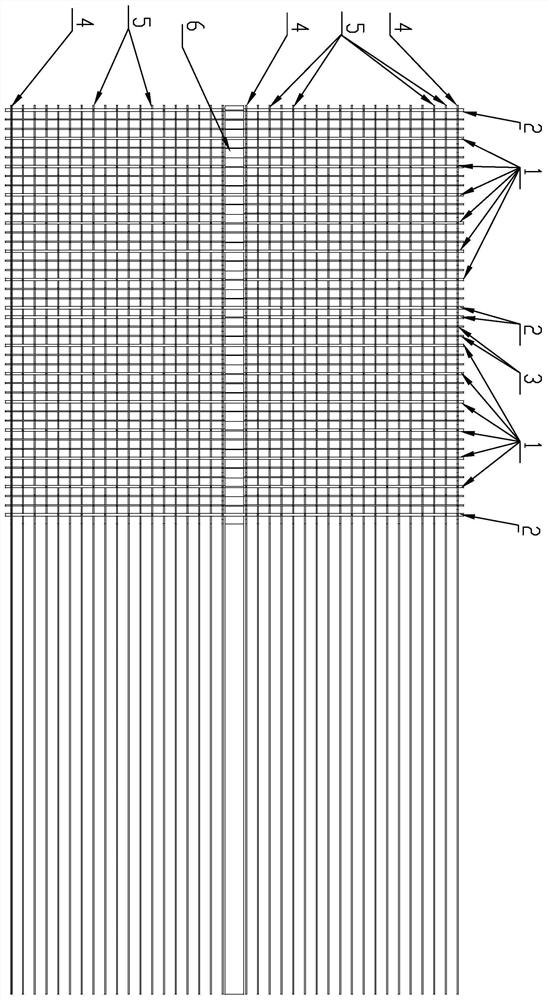
[0052] Such as image 3 Shown, a kind of lead-acid storage battery uses the lead mesh grid, comprises the grid body that is woven by the warp thread and the weft thread, has included in the grid body a plurality of independent grids adjacent to the left and right and up and down (that is, used for lead The grid of the size required by an independent piece of pole plate in the acid battery is an independent grid); the lead grid coating area formed by the grid body is at the boundary of its adjacent independent grid division, along its Thick plastic wires or thick lead wires are arranged in the parallel direction to form a frame (located at the boundary position of each independent grid) extending along the parallel direction of each independent grid. This embodiment can adopt thick plastic wire wefts 2 as forming The weft line of the frame; the lead mesh coating area formed by the grid body is provided with thick plastic wires, or thick lead acid, or several fine plastic wire s...
Embodiment 2
[0062] as attached Figure 4 Shown:
[0063] 1. The positive grid fabric is composed of:
[0064] Fabric composition in the weft direction (left and right): each independent grid contains a total of 6 conductive thick lead wire wefts 1, and the core wire of the lead wire is glass fiber, which is coated with 0.8SnPb alloy by extrusion to form a diameter coaxial with the core wire 1.2mm composite lead wire; a PP plastic weft 3 with a diameter of 0.8mm is woven between two adjacent thick lead wire wefts 1, and each independent grid contains 7 fine plastic wefts 3; each grid contains a diameter There are two 1.5mm thick plastic wefts 2 in total. The thick plastic wefts form the left and right frames of the grid to limit the vertical expansion of the lead plaster and the thick lead wire wefts 1. The material is PP.
[0065] Fabric composition in warp direction (upper and lower): each independent grid contains 5 thin plastic warp threads (thin PP plastic warp threads) with a diame...
Embodiment 3
[0070] as attached Figure 4 Shown:
[0071] 1. The positive grid fabric is composed of:
[0072]Fabric composition in the weft direction (left and right): each grid contains 6 conductive thick lead wire wefts 1, the core wire of the thick lead wire weft is glass fiber, and the 1.2SnPb alloy is coated by extrusion to form a coaxial wire with the core wire. Composite lead wire with a diameter of 1.2mm; a thick plastic weft thread (ABS plastic weft thread) 3 with a diameter of 0.8mm is woven between two adjacent thick lead wire weft threads 1, and each grid contains a total of 7 fine plastic weft threads 3; The grid contains two thick plastic wefts 2 with a diameter of 1.5 mm. The thick plastic wefts form the left and right borders of the grid to limit the expansion of the lead paste and the thick lead wire wefts 1 in the vertical direction. The material is ABS.
[0073] Fabric composition in warp direction (upper and lower): each grid contains 5 thin plastic warps (thin PP pl...
PUM
| Property | Measurement | Unit |
|---|---|---|
| thickness | aaaaa | aaaaa |
| width | aaaaa | aaaaa |
| diameter | aaaaa | aaaaa |
Abstract
Description
Claims
Application Information
 - R&D Engineer
- R&D Manager
- IP Professional
- Industry Leading Data Capabilities
- Powerful AI technology
- Patent DNA Extraction
Browse by: Latest US Patents, China's latest patents, Technical Efficacy Thesaurus, Application Domain, Technology Topic, Popular Technical Reports.
© 2024 PatSnap. All rights reserved.Legal|Privacy policy|Modern Slavery Act Transparency Statement|Sitemap|About US| Contact US: help@patsnap.com