
Cable-stayed bridge girder connected with anchor pulling plate

An anchor pull plate and main beam technology, applied in bridges, bridge materials, bridge construction and other directions, can solve problems such as easy occurrence of diseases, increase in bridge width, and difficulty in repairing and maintaining bridge air nozzles.

Inactive Publication Date: 2020-10-30
CHINA RAILWAY ERYUAN ENG GRP CO LTD
View PDF9 Cites 1 Cited by
  • Summary
  • Abstract
  • Description
  • Claims
  • Application Information

AI Technical Summary

Problems solved by technology

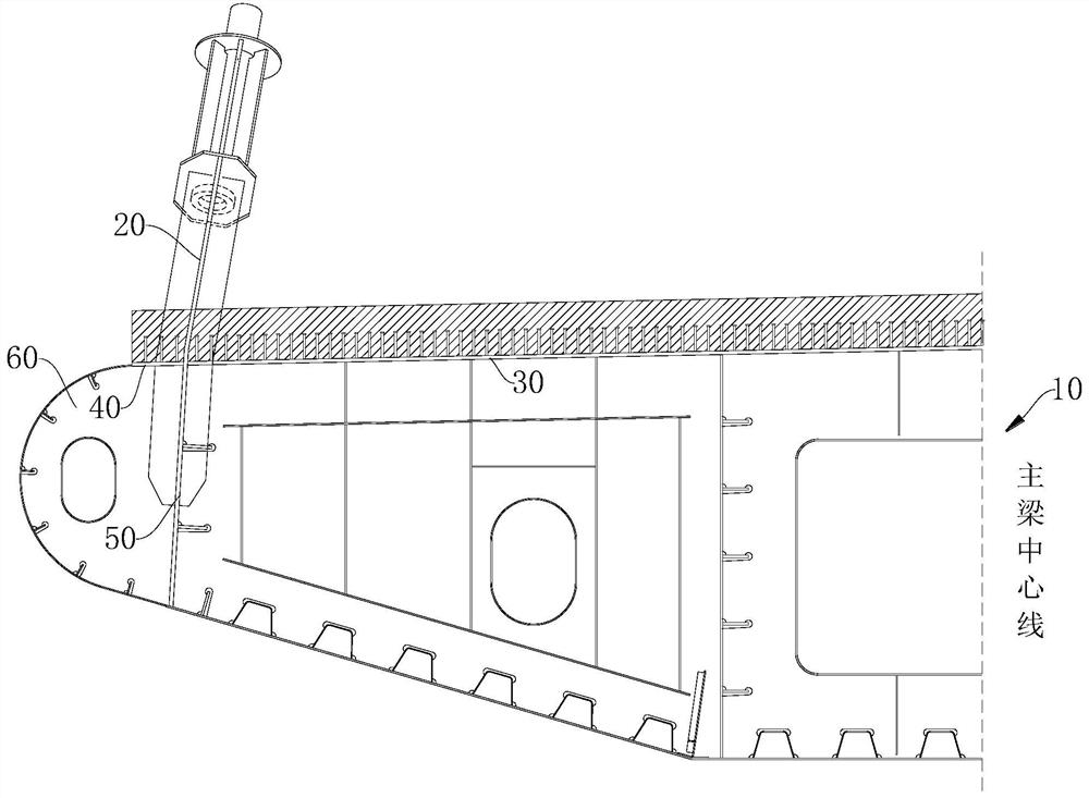
Since the air nozzle 60 is provided on the outer side of the side web 50, the horizontal top plate 30 needs to be provided with a cantilever end (that is, a cantilever steel plate 40) to connect the air nozzle 60, which not only increases the width of the bridge, but also increases the amount of steel used for the main girder. The amount of steel is relatively high, and since the air nozzle 60 is suspended in the air, maintenance personnel cannot reach the position of the air nozzle, which will bring certain difficulties to the repair and maintenance of the bridge air nozzle in the later stage
[0004] At the same time, due to the setting of the outer cantilever end, the anchor plate 20 needs to be welded on the top plate 30 with a cross weld, or the top plate 30 is opened to allow the side web 50 to pass through and then welded to the anchor plate 20. Both connection methods are butt welding The quality requirements are very high, and the fatigue strength of the weld is low, which is prone to disease, which is not good for the safety of the bridge

Method used


Image

  • Cable-stayed bridge girder connected with anchor pulling plate
  • Cable-stayed bridge girder connected with anchor pulling plate
  • Cable-stayed bridge girder connected with anchor pulling plate

Examples


Embodiment 1

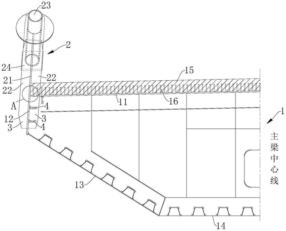
[0032] A main girder of a cable-stayed bridge connected with anchor slabs, such as Figure 2-4 As shown, it mainly includes steel-concrete composite beam 1 and anchor plate assembly 2:

[0033] Steel-concrete combined beam 1 is mainly composed of upper web 12, top plate 11, lower inclined web 13, bottom plate 14, and stiffeners on each plate. The plates are welded to each other to form a single-box single-chamber symmetrical structure, such as figure 2 . Both sides of the top plate 11 are respectively connected to the upper web 12 (only half of which is shown in the figure), and the upper web 12 is connected to the downward inclined web 13 in turn, and the downward inclined web 13 is arranged on both ends of the bottom plate 14, and the bottom plate 14 is opposite to the top plate 11; The combination of the web and the downward sloping web forms a streamlined section, which can reduce the wind resistance area and has good wind resistance. By adjusting the thickness of each ...


PUM


Abstract

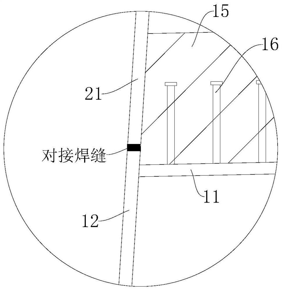
The invention relates to the field of bridge structure buildings, and particularly relates to a cable-stayed bridge girder connected with an anchor pulling plate. The cable-stayed bridge girder comprises a steel-concrete composite beam and an anchor pulling plate assembly which are connected, the steel-concrete composite beam comprises a top plate and an upper web which are connected, the anchor pulling plate assembly comprises the anchor pulling plate, the upper web is vertically connected to the end of the top plate, and the upper web extends out of the top plate and is in butt joint with the anchor pulling plate. According to the cable-stayed bridge girder, the structural form, stress, wind resistance and the like of the anchoring plate and the steel-concrete composite beam are comprehensively considered; the section form of the main beam structure, the connection mode of the main beam structure and the anchor pulling plate and the like are optimally designed; therefore, the adverseconditions of material waste, large construction hoisting weight and the like can be avoided, meanwhile, under the condition that the wind resistance of the bridge is guaranteed, the steel consumption and the construction cost are saved, butt weld joints are adopted between the anchor pulling plates and the upper web of the main beam, and the advantages of being better in stress, easier to guarantee the welding quality and the like are achieved.

Description

technical field [0001] The invention relates to the field of bridge structure construction, in particular to a main girder of a cable-stayed bridge connected with an anchor stay plate. Background technique [0002] In recent years, my country's infrastructure construction has achieved world-renowned achievements, and super projects such as expressways and high-speed railways continue to emerge. As a long-span bridge scheme, cable-stayed bridges have played an important role in these projects. The engineering technology of cable-stayed bridges has also been continuously innovated and developed. Reasonable main girder cross-section forms, safe and reliable cable-stayed cables and main girder anchorages are adopted. The method and so on are the technical issues that the design focuses on. The anchor plate, as the main stress-bearing member connecting the stay cable and the steel girder, is the main stress-bearing point of the whole bridge. The anchor plate is different from t...

Claims


Application Information

Patent Timeline
IPC IPC(8): E01D11/02E01D19/14E01D2/04
CPCE01D2/04E01D11/02E01D19/14E01D2101/268
Inventor 王应良秦煜秦羽曾忠曹洪武袁明
Owner CHINA RAILWAY ERYUAN ENG GRP CO LTD
Learn More