
Automatic clearing method and automatic clearing device of spinning frame

An automatic cleaning and spinning frame technology, applied in textiles and papermaking, etc., can solve the problems of cutter collision, affecting the safe production of spinning frames, and affecting the efficient use of yarn cutters, etc.

Pending Publication Date: 2020-10-30
ANQING NORMAL UNIV
View PDF10 Cites 3 Cited by
  • Summary
  • Abstract
  • Description
  • Claims
  • Application Information

AI Technical Summary

Problems solved by technology

[0004] The above-mentioned patents are only applicable to some spinning frames whose spindles are not driven by belts, which has limitations. However, the spinning frames that rely on belts to drive the spindles to rotate are difficult to install the automatic yarn clearing device due to the limited space behind the spindles; at the same time, the yarn cutter The cutter is fixed on one side of the spindle, and it is difficult to adjust the distance between the cutter on the yarn cutter and the spindle. When the thickness of the tail yarn wound on the spindle is too large, and the cutter of the yarn cutter moves to When the A position of the next spindle is reached, it is easy to cause the cutter to hit the high-speed rotating spindle, which will cause damage to the yarn cutter, which not only affects the efficient use of the yarn cutter, but also affects the safe production of the spinning frame

Method used

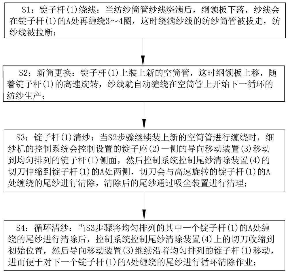

Image

  • Automatic clearing method and automatic clearing device of spinning frame
  • Automatic clearing method and automatic clearing device of spinning frame
  • Automatic clearing method and automatic clearing device of spinning frame

Examples


Embodiment approach

[0041] As an embodiment of the present invention, a collection cavity 61 is opened inside the elastic buffer plate 6, and a dust suction hole 62 is opened on the outer wall of the collection cavity 61; the bottom end of the collection cavity 61 is connected with a suction hose 7, and the dust suction hose 7 is connected with the vacuum cleaner attached to the spinning frame; when the cutting knife 5 cuts and cleans the tail thread wound on the outer wall of the spindle bar 1, due to the rotation of the end of the conical bent piece 52 and the spindle bar 1 The direction is opposite, and then when the conical bent piece 52 removes the tail wire wound on the spindle rod 1, the tail wire will hit the elastic buffer plate 6 under the high-speed centrifugal force of the spindle rod 1, and then the suction force of the vacuum cleaner will pass through the suction. The dust hose 7 sucks the dust generated by the tail line into the collection chamber 61 through the dust suction hole 62...


PUM


Abstract

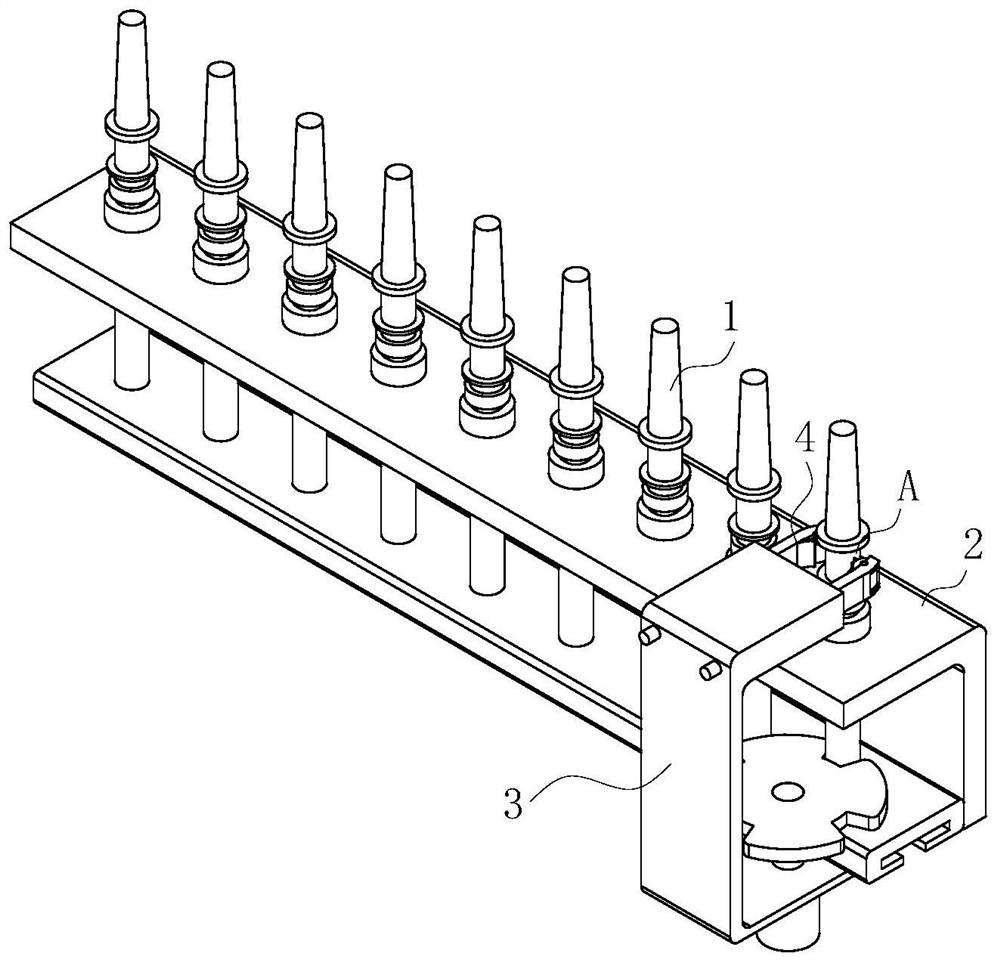
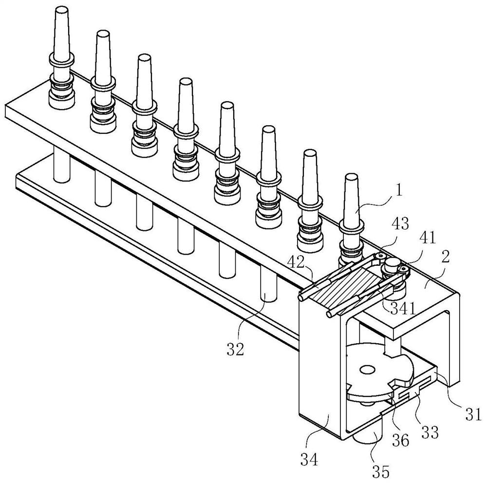
The invention belongs to the technical field of ring spinning, in particular to an automatic clearing method and an automatic clearing device of a spinning frame. Spindle connecting rods are evenly fixed to the upper end face of a guide sliding rail, and the spindle connecting rods are rotationally connected with the bottom ends of spindle rods. A sliding block is arranged inside the guide slidingrail in a sliding manner. An installation base is fixed to the side wall of the sliding block. A miniature motor is installed on the bottom end face of the installation base. A rotary wheel disk is in engagement with the spindle connecting rods which are evenly arranged. Sliding chambers are symmetrically formed in the upper-end side wall of the installation base. Sliding supporting strips are rotationally installed in the sliding chambers respectively. One end of each sliding supporting strip is connected to a telescopic end of an electric telescopic rod. Clearing barrels are fixed to the ends of the sliding supporting strips which are arranged in the shape of arcs through fixing columns. A cutter is fixedly arranged on the side wall of each clearing barrel. The automatic clearing devicecan carry out stable and efficient clearing operation on the spindle rods which are evenly arranged; and because a guide movement device is arranged on the side face of a spindle base, the space occupied by the automatic clearing device is reduced.

Description

technical field [0001] The invention belongs to the technical field of ring spinning, in particular to an automatic yarn clearing method and an automatic yarn clearing device for a spinning frame. Background technique [0002] In the production process of the ring spinning frame, the spindle foot of the spindle is often wrapped with some tail yarn. After many times of doffing, a layer of yarn will be wound and piled up on the spindle, covering the knurling, so that the friction at A will be lost, which will lead to During subsequent doffing, the yarn slips and cannot be wound, which affects spinning production. [0003] The Chinese patent discloses an automatic cleaning device for the spindle tail of a collective doffing spinning frame. The patent application number is 2015101312109. The driving mechanism includes a motor, a transmission belt, a driving wheel and a driven wheel. The end is connected with the driving wheel, the passive wheel is installed on the other side of...

Claims


Application Information

Patent Timeline
IPC IPC(8): D01H11/00
CPCD01H11/00
Inventor 梁波吴琼施子珍倪俊龙江伟胡媛媛黄忠刘娟朱柱王远志
Owner ANQING NORMAL UNIV
Learn More