
Printing device and method

A technology of printing equipment and printing unit, applied in printing and other directions, can solve problems such as ink breakage, low ink pressure, ink overflow, etc., and achieve the effect of improving printing quality

Pending Publication Date: 2020-10-30
SHANGHAI REALFAST DIGITAL TECH CO LTD
View PDF0 Cites 3 Cited by
  • Summary
  • Abstract
  • Description
  • Claims
  • Application Information

AI Technical Summary

Problems solved by technology

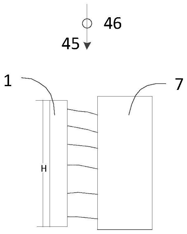
[0004] In the actual printing process, the ink droplets ejected from the print head are not necessarily vertically downward, for example figure 1 In the situation shown, the inkjet printing head 1 sprays sideways against the side of the printing medium 7. Due to the influence of gravity, the ejected trajectory of the ink droplets will be curved to a certain extent. However, since the printing head itself has a certain height H, The lower nozzle hole is under the pressure of the ink from above, and the higher pressure of the lower nozzle hole makes the trajectory of the ink droplet ejected from the lower nozzle hole less curved than the ink droplet ejected from the upper nozzle hole, resulting in poor quality of the printed pattern. good
In addition, the higher pressure of the lower nozzle holes makes the lower nozzle holes prone to ink overflow during the printing process, resulting in poor quality of printed patterns
Due to the height H of the print head itself, affected by gravity, the upper nozzle hole has a lower ink pressure than the lower nozzle hole, and it is easy to break the ink during the printing process, resulting in poor quality of the printed pattern.

Method used


Image

  • Printing device and method
  • Printing device and method
  • Printing device and method

Examples


Embodiment Construction

[0023] In the description of this patent, it should be clarified that the terms "center", "upper", "lower", "left", "right", "vertical", "horizontal", "inner", "outer", etc. The indicated orientation or positional relationship is based on the orientation or positional relationship shown in the drawings, and is only for the convenience of describing the present invention and simplifying the description, rather than indicating or implying that the referred device or element must have a specific orientation, or in a specific orientation. construction and operation, and therefore cannot be construed as limiting the present invention; the terms "first", "second", and "third" are used for descriptive purposes only, and cannot be construed as indicating or implying relative importance; in addition, unless otherwise Clearly stipulated and limited, the terms "installation", "connection" and "connection" should be understood in a broad sense, for example, it can be a fixed connection, a ...


PUM

PropertyMeasurementUnit
Lengthaaaaaaaaaa

Abstract

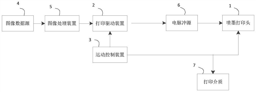
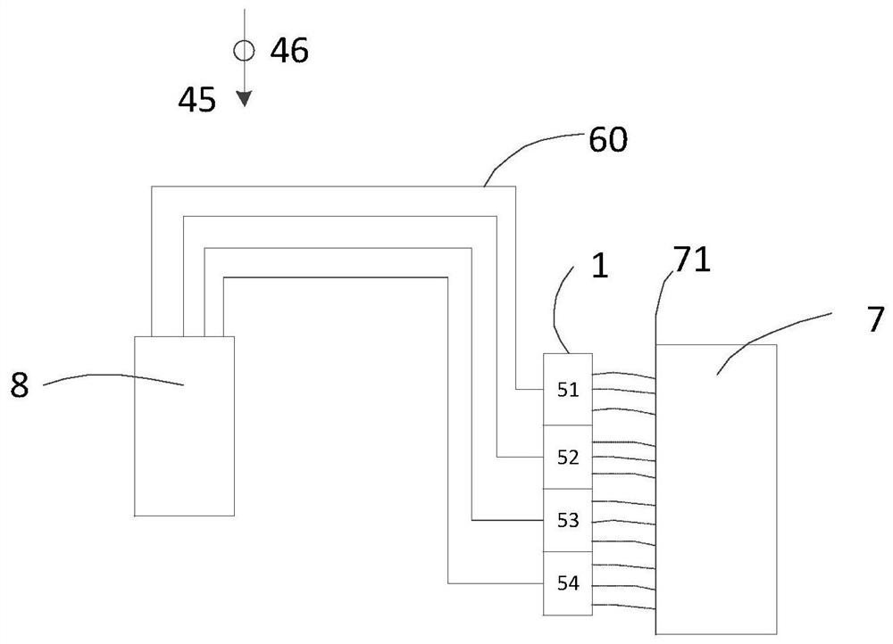
The invention provides a printing device. The printing device comprises an ink box for providing ink, at least one ink jet print head, a printing medium, a printing driving device, a motion control device and an image processing device, wherein each ink jet print head at least comprises two printing units, the printing units are arranged in a first direction, and each printing unit is connected with the ink box through a channel; the printing medium is disposed opposite to the ink jet print heads; the printing driving device for controlling the ink jet printing heads to print on the printing medium; the motion control device controls relative motion of the ink jet print heads and the print medium in a horizontal direction; and the image processing device transmits image information to be printed to the print driving device. According to the printing device provided by the invention, the ink jet print heads are divided into the multiple printing units, each printing unit is independently supplied with ink, so that the pressure of the ink received by each printing unit is basically consistent, the tracks of the ink during side-jet printing are basically consistent, and the printing quality is improved.

Description

technical field [0001] The invention relates to the technical field of inkjet printing, in particular to a printing device and method. Background technique [0002] Inkjet printing is usually done with drop-on-demand or continuous inkjet printing. In drop-on-demand printing, droplets are ejected onto a recording medium using a drop ejector with a pressurized (eg, thermal or piezoelectric) driver. Selectively activating the driver causes formation and ejection of a flying ink drop that travels through the space between the printhead and the recording medium and impacts the recording medium. The formation of the printed image is achieved by controlling the formation of each droplet according to the need to print the desired image. The desired image may include any dot pattern corresponding to the image data. It can include graphics or text images. If appropriate inks are used, it can also include dot patterns or three-dimensional structures for printing useful functional d...

Claims


Application Information

Patent Timeline
IPC IPC(8): B41J2/01B41J2/175
CPCB41J2/01B41J2/17513B41J2/17556
Inventor 谢永林
Owner SHANGHAI REALFAST DIGITAL TECH CO LTD
Learn More