
Hydraulic device for composite board production

A technology of hydraulic device and composite board, which is applied in the direction of lamination device, lamination, and layered products, etc., can solve the problems of damage to the surface of raw materials, inability to clean dust on the surface of raw materials, and inability to meet the processing of composite boards.

Active Publication Date: 2020-10-30
安徽润象新材料科技有限公司
View PDF7 Cites 1 Cited by
  • Summary
  • Abstract
  • Description
  • Claims
  • Application Information

AI Technical Summary

Problems solved by technology

[0003] Composite boards need to be pressed by hydraulic devices during production. General hydraulic devices can only process one type of composite boards, and cannot meet the processing of composite boards with flat or corrugated surfaces. At the same time, general hydraulic devices cannot The realization of automatic limit and fixation of raw materials leads to the problem of deviation during processing, and the existing hydraulic device cannot clean the dust on the surface of raw materials. If there are foreign particles on the surface of raw materials, it is easy to cause damage to the surface of raw materials, and the general The air blowing device cannot adjust the wind direction. Therefore, a hydraulic device for composite panel production is proposed to solve the above problems.

Method used


Image

  • Hydraulic device for composite board production
  • Hydraulic device for composite board production
  • Hydraulic device for composite board production

Examples


Embodiment 1

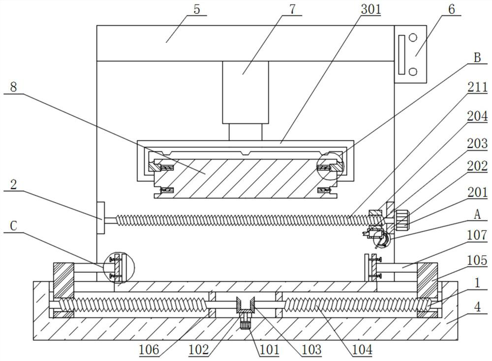
[0025] see Figure 1-5 , the present invention provides a technical solution:

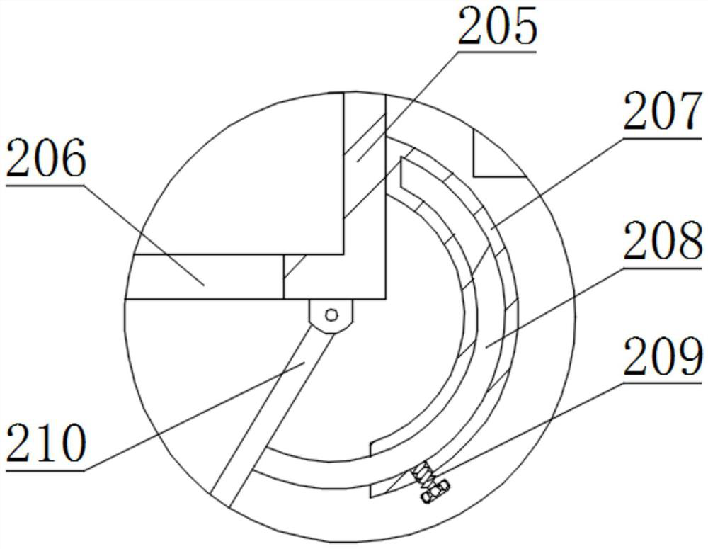
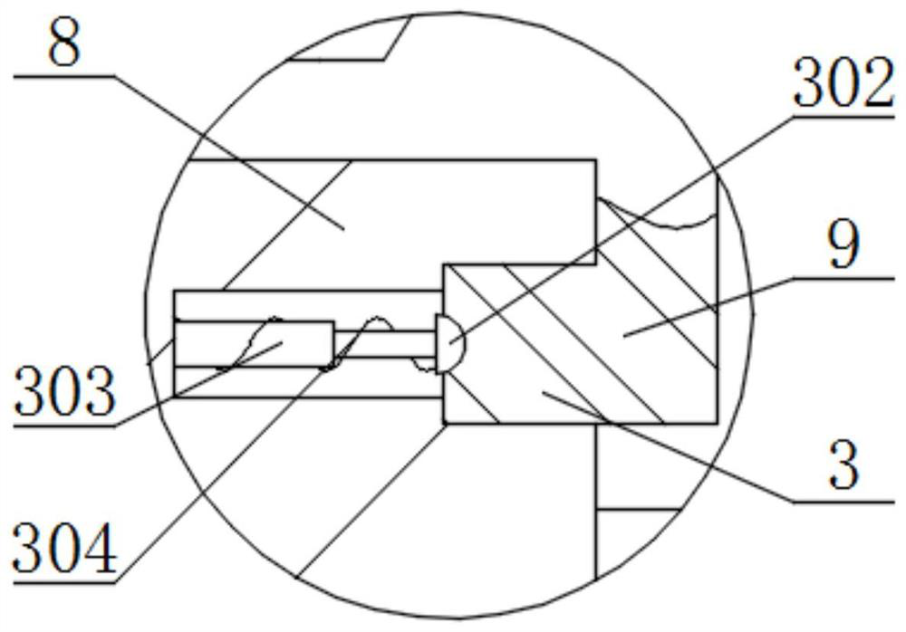
[0026] A hydraulic device for composite board production, comprising a bottom plate 4 and a connecting frame 5, the top end of the bottom plate 4 is fixedly connected with a connecting frame 5, the inner side of the top end of the connecting frame 5 is fixedly connected with a hydraulic rod 7, and the bottom end of the hydraulic rod 7 is fixedly connected with a Connecting device 3, one end of the connecting device 3 is fixedly connected with the first pressure plate 8, the inner side of the first pressure plate 8 is engaged with the second pressure plate 9, the right end of the connecting frame 5 is fixedly connected with the controller 6, and the front end of the connecting frame 5 is fixedly connected There is an air blowing device 2, and the inner side of the bottom end of the bottom plate 4 is fixedly connected with the limiter 1, and the limiter 1 includes a first motor 101, a first bevel gea...

Embodiment 2

[0029] In embodiment 2, the same parts as in embodiment 1 will not be repeated. The difference is that when the corrugated composite board needs to be pressed, the staff takes off the second press plate 9 located on the upper side of the first press plate 8 , and then placed and engaged with the chuck 302 on the lower side of the first press plate 8, so as to realize the pressing of the raw material through the second press plate 9.


PUM


Abstract

The invention relates to the technical field of composite board production, in particular to a hydraulic device for composite board production. The hydraulic device comprises a bottom plate and a connecting frame; the inner side of the bottom end of the bottom plate is fixedly connected with a limiting device; the limiting device comprises a first motor, a first bevel gear, a second bevel gear, afirst lead screw, a first sliding block, a fixing block, a push rod, a connecting plate, push plates, a limiting rod, a first spring and a blocking disc; the inner side of the bottom end of the bottomplate is fixedly connected with the first motor; the tail end of a main shaft of the first motor is fixedly connected with the first bevel gear; in the present invention, the first bevel gear, the first lead screw, the first sliding block, the push rod, the connecting plate, the push plates, the limiting rod and the blocking disc are arranged; through the effect of the first lead screw, a left push plate and a right push plate can clamp and fix raw materials at the same time, it is guaranteed that the raw materials cannot deflect in the pressing process, meanwhile, the push plates can make slow contact with the raw materials through first springs, and the push plates are prevented from instantaneously extruding the raw materials.

Description

technical field [0001] The invention relates to the technical field of composite board production, in particular to a hydraulic device for composite board production. Background technique [0002] Composite panels are generally divided into: metal composite panels, wood composite panels, color steel composite panels, rock wool composite panels, etc. Composite panels are generally divided into metal composite panels, wood composite panels, color steel composite panels, rock wool composite panels, etc. It refers to covering one metal plate with another metal plate to achieve the effect of saving resources and reducing costs without reducing the use effect (corrosion resistance, mechanical strength, etc.). The compound method usually includes explosive compound method. Explosive rolling compounding, rolling compounding, etc. Composite materials can be divided into composite plates, composite pipes, composite rods, etc., which are mainly used in anti-corrosion, pressure vessel m...

Claims


Application Information

Patent Timeline
Patent Type & Authority Applications(China)
IPC IPC(8): B32B37/10B32B38/18B32B38/16
CPCB32B37/10B32B38/1841B32B38/162
Inventor 张劼
Owner 安徽润象新材料科技有限公司
Learn More