
Continuous machining equipment for probe

A processing equipment and probe technology, applied in metal processing equipment, metal processing, metal processing mechanical parts, etc., can solve the problems of inability to guarantee processing continuity, waste of time, manpower and material resources, etc., to facilitate monitoring and viewing, improve efficiency, Structured novel effect

Pending Publication Date: 2020-10-30
杭州中允科技有限公司
View PDF0 Cites 2 Cited by
  • Summary
  • Abstract
  • Description
  • Claims
  • Application Information

AI Technical Summary

Problems solved by technology

[0002] processed as Figure 10 For the probe shown, one end of the probe needs to be slotted, flattened, and narrowed, and the other end needs to be drilled first to break the outer wall of the shaft end, and then mill a U-shaped notch at the broken position. Some processing equipment is split. The processing of the probe is first processed on one device, and then manually transferred to another device to process the other part. This cannot guarantee the continuity of processing, the monitoring of the processing process and A lot of time and manpower and material resources will be wasted in the transfer process of the probe

Method used


Image

  • Continuous machining equipment for probe
  • Continuous machining equipment for probe
  • Continuous machining equipment for probe

Examples


Embodiment Construction

[0033]The technical solutions of the present invention will be clearly and completely described below in conjunction with the accompanying drawings. Apparently, the described embodiments are some of the embodiments of the present invention, but not all of them. Based on the embodiments of the present invention, all other embodiments obtained by persons of ordinary skill in the art without making creative efforts belong to the protection scope of the present invention.

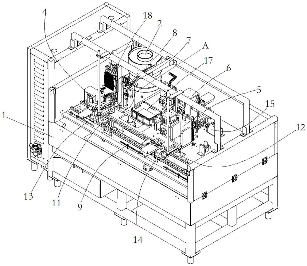
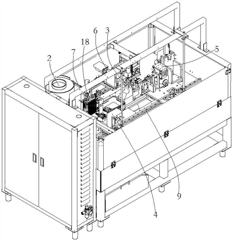
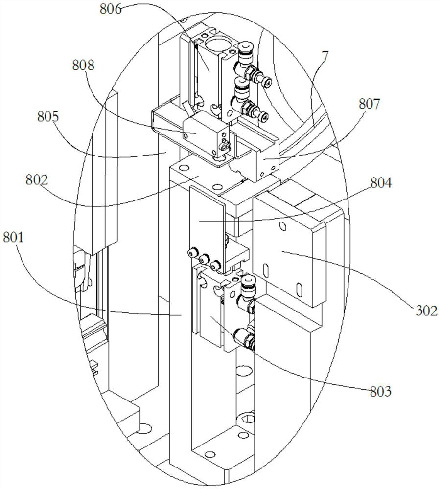
[0034] like Figure 1-9 As shown, the present invention provides a continuous processing device for probes, including an electric control box 1, a discharge vibrating plate 2, a positioning mechanism 3, a retrieving mechanism 4, a first shaft end processing mechanism 5, a second shaft End processing mechanism 6;

[0035] The discharge vibrating plate 2 is arranged on the side of the upper end face of the electric control box body 1, the discharge end of the discharge vibrating plate 2 is provided with an incli...


PUM


Abstract

The invention discloses continuous machining equipment for a probe. The continuous machining equipment comprises an electronic control box, a discharging vibration disc, a positioning mechanism, a taking mechanism, a first shaft end machining mechanism and a second shaft end machining mechanism. The discharging vibration disc is arranged beside the upper end face of the electronic control box, andan inclined sliding groove is formed in the discharging end of the discharging vibration disc. A receiving mechanism connected with the sliding groove is arranged at the lower end of the sliding groove. The positioning mechanism is arranged in the middle of the upper end face of the electronic control box, and is used for clamping materials. The taking mechanism comprises a first servo driving mechanism, a first pneumatic finger and a second pneumatic finger. The first shaft end machining mechanism and the second shaft end machining mechanism are used for machining the two shaft ends, for clamping the materials, of the positioning mechanism. The continuous machining equipment is novel in structure, high in automation degree and smooth in joint of the whole process, the machining continuity is guaranteed, the step of transferring the probe is saved, time, manpower and material resources are saved, and efficiency is improved.

Description

technical field [0001] The invention relates to the technical field of automatic processing, in particular to a continuous processing equipment for probes. Background technique [0002] processed as Figure 10 For the probe shown, one end of the probe needs to be slotted, flattened, and necked, and the other end needs to be punched first, the outer wall of the shaft end needs to be broken, and then a U-shaped notch is milled at the broken position. Some processing equipment is split. The processing of the probe is first processed on one equipment, and then manually transferred to another equipment to process another part. This cannot ensure the continuity of processing, monitoring of the processing and A lot of time and manpower and material resources are wasted in the process of probe transfer. SUMMARY OF THE INVENTION [0003] The purpose of the present invention is to provide a continuous processing apparatus for probes to solve the problems raised in the above backgro...

Claims


Application Information

Patent Timeline
Patent Type & Authority Applications(China)
IPC IPC(8): B23P23/06B23Q3/08B23Q7/04B23Q11/00
CPCB23P23/06B23Q3/08B23Q7/04B23Q11/0042
Inventor 傅强黄登杰
Owner 杭州中允科技有限公司
Learn More