Flue gas dust removal equipment for atmospheric pollution control

A technology of dust removal equipment and flue gas, which is applied in the direction of dispersed particle filtration, combined device, filtration and separation, etc., can solve the problems of reducing the speed of flue gas emission and the speed of flue gas, and achieve the effect of increasing the speed

Pending Publication Date: 2020-10-30
闵亚红
View PDF6 Cites 3 Cited by
  • Summary
  • Abstract
  • Description
  • Claims
  • Application Information

AI Technical Summary

Problems solved by technology

[0003] When the flue gas after heat exchange is processed, the method of foam spraying is usually used for dust removal. The liquid is sprayed onto the dispersion plate. When the gas passes through the dispersion plate, foam is generated between the liquid on the dispersion plate and the gas passes through the foam. , so as to remove the dust in the gas. Due to the continuous introduction of the gas, the gas has a certain flow velocity, and it will rise with the foam during the rising process. Finally, the dust-stained foam will be separated from the gas through the filler and the gas will be separated. Release, because the foam has a certain viscosity, the separated foam sticks to the bottom of the filler, and with the progress of dust removal, the foam at the bottom of the filler gradually increases, covering the air intake gap at the bottom of the filler, so that the smoke cannot pass through quickly Packing, which reduces the speed of flue gas emission

Method used


Image

  • Flue gas dust removal equipment for atmospheric pollution control
  • Flue gas dust removal equipment for atmospheric pollution control
  • Flue gas dust removal equipment for atmospheric pollution control

Examples


Embodiment 1

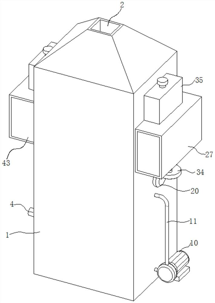
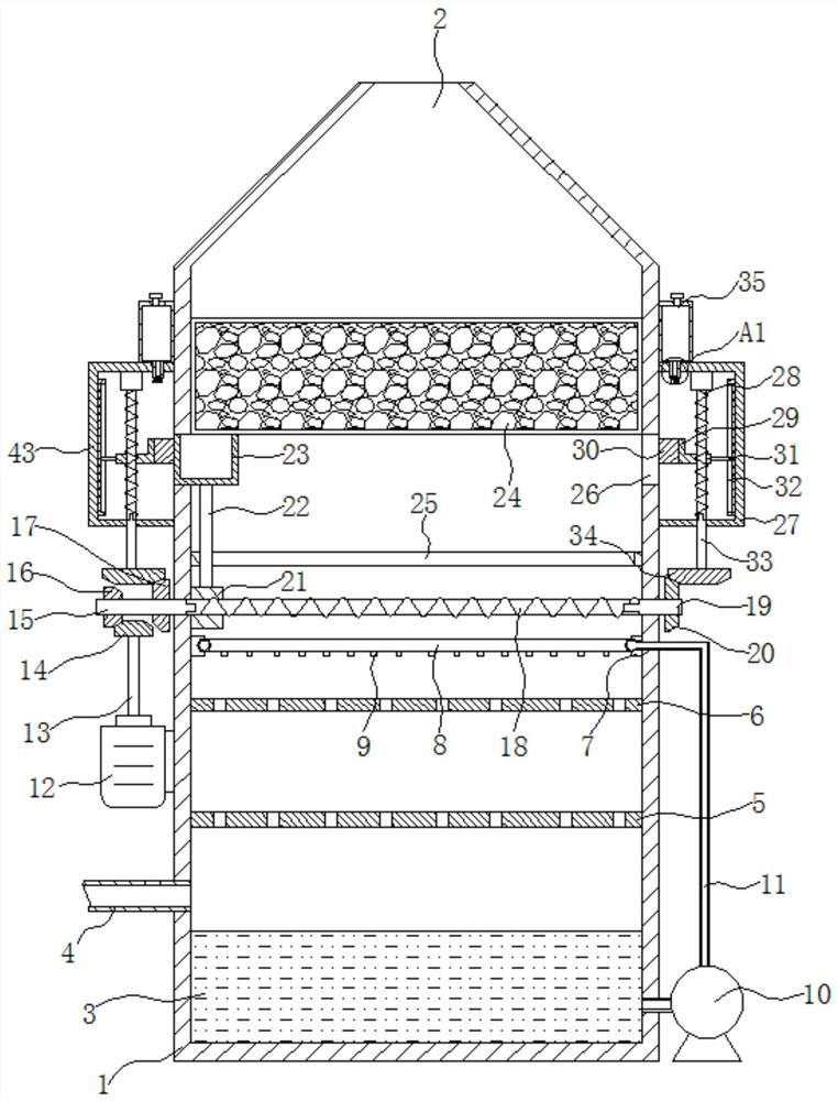
[0027] refer to Figure 1-9 , a flue gas dedusting device for air pollution prevention and control, comprising a treatment box 1, the top of the treatment box 1 is provided with an air outlet 2, the function of the air outlet 2 is to discharge the flue gas after dust removal, and the inner bottom of the treatment box 1 is placed with The liquid medicine layer 3 is connected with an air intake pipe 4 on the treatment box 1. The function of the air intake pipe 4 is to introduce the flue gas after heat exchange and cooling into the treatment box 1. Connected with a first perforated plate 5, the function of the first perforated plate 5 is to disperse the smoke, so that the smoke is evenly in contact with the second perforated plate 6, the first perforated plate 5 is located above the intake pipe 4, and the processing The second perforated plate 6 is connected in the case 1, and the effect of the second perforated plate 6 is to disperse the liquid medicine sprayed by the spraying m...

Embodiment 2

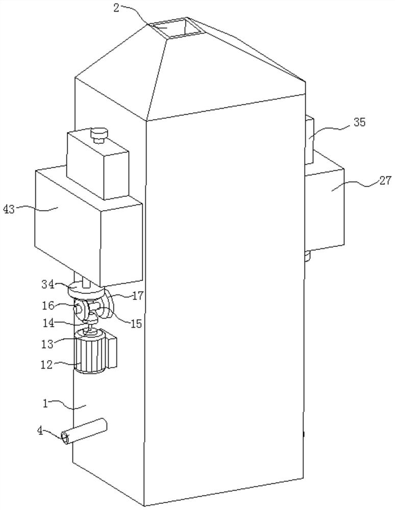
[0034] After the power mechanism is powered on, it drives the second rotating shaft 15 to rotate, and the second rotating shaft 15 drives the first reciprocating screw 18 to rotate. The first moving block 21 drives the scraper 23 to reciprocate in the horizontal direction through the support rod 22. When the foam bonded to the lower surface of the filler 24 is scraped off, due to the certain viscosity of the foam, when the scraper 23 scrapes off the foam bonded to the lower surface of the filler 24, the foam adhered to both sides of the scraper 23 will More and more, when the scraper 23 scrapes off the foam on the lower surface of the filler 24, the foam adhering to both sides of the scraper 23 adheres to the lower surface of the filler 24 again, again covering the air intake gap on the lower surface of the filler 24. , therefore, referring to Figure 1-9 , as another preferred embodiment of the present invention, on the basis of embodiment 1, both sides of processing box 1 ar...

Embodiment 3

[0038] When the foam on the side of the scraper 23 was adsorbed by the elastic block 30, because the foam remover on the elastic block 30 was limited, after a period of time, the foam remover on the elastic block 30 gradually decreased until completely consumed, and the elasticity When the block 30 cannot absorb the foam on the side of the scraper 23, it is necessary to add a foam remover, refer to Figure 1-9 On the basis of Embodiment 2, the upper end of the first box body 27 is communicated with the first medicine dispensing mechanism. Two medicine dispensing mechanisms, the effect of the second medicine dispensing mechanism is to add foam eliminator for the second wiping mechanism, the first medicine dispensing mechanism is identical in structure with the second medicine dispensing mechanism, the first medicine dispensing mechanism comprises medicine storage box 35, medicine storage The function of the box 35 is to store the foam eliminating agent, and the medicine storage...


PUM


Abstract

The invention relates to the technical field of flue gas dust removal, especially to flue gas dust removal equipment for atmospheric pollution prevention and control. The flue gas dust removal equipment comprises a treatment box, wherein one end of a first reciprocating screw is connected with a third rotating shaft; a fourth bevel gear is connected to the end, located on the outer side of the treatment box, of the third rotating shaft; a first moving block is connected to the first reciprocating screw; a first limiting frame is arranged in and connected with the treatment box; a scraping plate is connected to the upper end of the supporting rod; a filler is arranged in and fixedly connected with the treatment box; the bottom end of the filler makes contact with the upper end of the scraping plate; and through holes are formed in the two sides of the treatment box. According to the invention, an external controller controls a power mechanism to start and then drives the second rotatingshaft to rotate; the first moving block reciprocates in a horizontal direction under limiting of a first limiting frame; the first moving block drives the scraping plate to reciprocate in the horizontal direction through the supporting rod; the reciprocating scraping plate scrapes foam bonded to the lower surface of the filler, so an air inlet gap in the bottom of the filler is not blocked, and asmoke discharging speed is increased.

Description

technical field [0001] The invention relates to the technical field of flue gas dedusting, in particular to a flue gas dedusting device for air pollution prevention and control. Background technique [0002] With the rapid development of industry, the high-temperature flue gas generated in the industrial production process needs to be dedusted before it can be discharged into the atmosphere. When the high-temperature flue gas generated in the industrial production process is treated, the high-temperature flue gas is first discharged into the heat exchanger Perform heat exchange, use the waste heat of high-temperature flue gas to add water to recycle the heat of high-temperature flue gas, and finally pass the heat-exchanged flue gas into the dust collection equipment for dust removal, and discharge it into the atmosphere after dust removal treatment. [0003] When the flue gas after heat exchange is processed, the method of foam spraying is usually used for dust removal. The ...

Claims


Application Information

Patent Timeline
Patent Type & Authority Applications(China)
IPC IPC(8): B01D50/00B01D46/00
CPCB01D2201/08B01D46/681B01D50/60
Inventor 不公告发明人
Owner 闵亚红
Why Eureka
Try Eureka