Sheep flock breeding individual sorting system
A sorting system and individual technology, applied in the field of animal husbandry group sorting, can solve the problems of difficult sorting, low sorting precision, and high degree of manual participation, and achieve the effect of improving the ability of sorting precision
- Summary
- Abstract
- Description
- Claims
- Application Information
AI Technical Summary
Problems solved by technology
Method used
Image
Examples
Embodiment 1
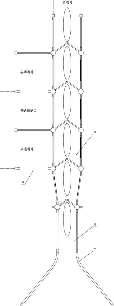
[0028] Embodiment 1: a kind of flock breeding individual sorting system adopts such as figure 1 The structural form shown, from figure 1 As can be seen in the figure, the system consists of a main channel and multiple sorting channels. A conical inlet 25 is provided at the inlet end of the main passage 27, and then a restricting passage 26 is connected, and the restricting passage 26 is used to compress the two side walls to ensure that only one sheep passes through. Then connect the main part of the main channel. Usually, the main channel is used as the output channel of the main group (normal group), and the sorting channel is used as the sorting channel of a small number of different groups.
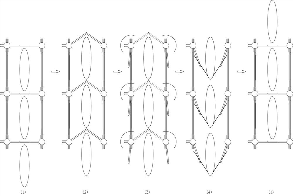
[0029] There are multiple detection areas in the main part of the main channel, figure 1 Take three detection areas as an example. Each detection area includes two side walls, and a pair of revolving door systems are respectively arranged in front of each detection area, and adjac...
Embodiment 2
[0037] Embodiment 2: On the basis of Embodiment 1, for the motion state of each revolving door system in a rotation cycle, such as figure 2 In step (4), the auxiliary pusher is set to automatically drive individual sheep forward. The side wall is provided with auxiliary thrust components such as Figure 4 Shown, comprise parts such as auxiliary push plate 17 and U-shaped link telescoping mechanism.
[0038] Specifically, a fixed seat 16 is installed on the inner side cross bar of the side wall, and the auxiliary push plate 17 is hinged on the fixed seat 16. In this embodiment, a plurality of horizontally parallel auxiliary push plates 17 pass through the vertical connecting plate in the middle. 19 are fixed together to form composite push plate. The U-shaped connecting rod telescopic mechanism is to be fixed with two pairs of guide sleeves 20, two U-shaped connecting rods 21 on the inner side cross bar of the side wall. The two wing bars of each U-shaped connecting rod 21 ...
Embodiment 3
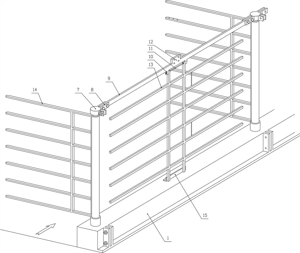
[0041] Embodiment 3: On the basis of Embodiment 1, the rotating column assembly in this embodiment is based on a rotatable drum 6 and a non-rotatable cylindrical fixed column, and a cylindrical fixed column is sleeved inside the rotary drum 6 . The lower end of the cylindrical fixed column is fixed in the corresponding lower sleeve in the base, and the upper end of the cylindrical fixed column is fixed with an upper sleeve. The two ends of the connecting rod 9 are respectively connected with the upper sleeves on the top of the front and rear adjacent rotating column assemblies.
[0042] The base 1 is provided with a drum base 29 for installing the drum 6, and the inner part of the drum 6 protruding into the base 1 is equipped with a compound pulley. The transmission mechanism arranged in the base 1 drives the rotating drum to rotate. Specifically, a composite pulley 4 is installed under each rotating drum 6, and the adjacent composite pulleys are connected by the same endless ...
PUM
 Abstract
Description
Claims
Application Information
 - R&D Engineer
- R&D Manager
- IP Professional
- Industry Leading Data Capabilities
- Powerful AI technology
- Patent DNA Extraction
Browse by: Latest US Patents, China's latest patents, Technical Efficacy Thesaurus, Application Domain, Technology Topic, Popular Technical Reports.
© 2024 PatSnap. All rights reserved.Legal|Privacy policy|Modern Slavery Act Transparency Statement|Sitemap|About US| Contact US: help@patsnap.com


