Cooling device

A cooling device, cooling rib technology, applied in cooling/ventilation devices, electromechanical devices, measuring devices, etc., can solve problems such as energy consumption

Pending Publication Date: 2020-10-27
ROBERT BOSCH GMBH
View PDF10 Cites 0 Cited by
  • Summary
  • Abstract
  • Description
  • Claims
  • Application Information

AI Technical Summary

Problems solved by technology

The disadvantage of this system is that the fan is in continuous operation and consumes energy to ensure adequate cooling of the sensor unit even in the presence of sufficient traffic wind

Method used


Image

  • Cooling device
  • Cooling device
  • Cooling device

Examples


Embodiment Construction

[0035] In the following description of exemplary embodiments of the present invention, identical elements are provided with the same reference numerals, wherein a repeated description of these elements is omitted where necessary. The figures represent the subject matter of the invention only schematically.

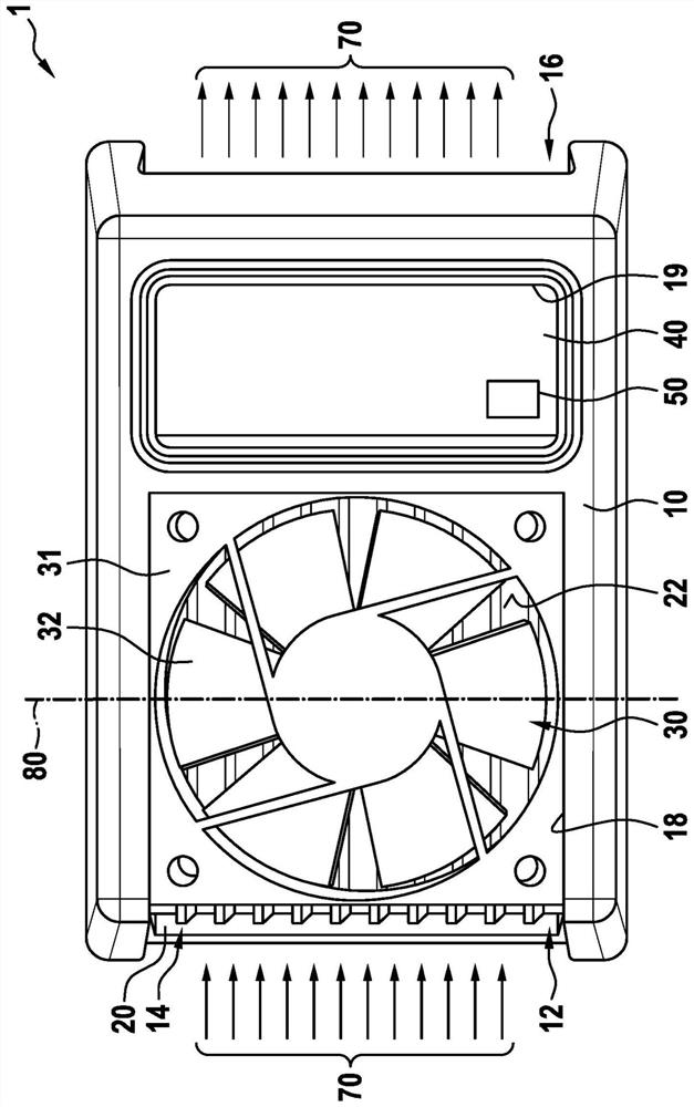
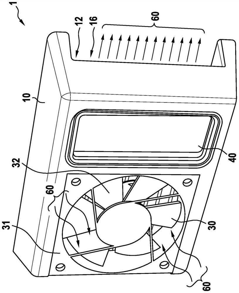
[0036] A possible embodiment of the cooling device 1 according to the invention is in figure 1 Shown in top view. exist figure 2 A cooling device 1 of identical construction is shown in oblique view.

[0037]The cooling device 1 comprises a housing frame 10 which is placed on a heat exchanger 20 and partially protrudes laterally therefrom. In this example, the heat exchanger 20 is configured in the form of a cooling plate and has a first surface 22 which faces the housing frame 10 . An electrically drivable fan unit 30 and a control unit 40 are respectively accommodated in the housing frame 10 in recesses 18 , 19 of the housing frame 10 . The fan unit 30 is arranged ...


PUM


Abstract

The invention relates to a cooling device (1) which comprises a housing frame (10), a heat exchanger (20), an electrically operatable fan unit (30), a control unit (40), and a sensor unit (50). The housing frame (10) can be arranged on a first surface of the heat exchanger (20) in particular. The fan unit (30), for example a fan or a ventilator, is arranged such that a first flow of air (60) is generated in the direction of the first surface (22) of the heat exchanger (20) when the fan unit (30) is operated. The fan unit (30) is received in a recess (18) of the housing frame (10) for example.According to the invention, the housing frame (10) has at least one air channel (12) with an air inlet opening (14) and an air outlet opening (16), wherein the air channel (12) is formed parallel to the first surface (22) of the heat exchanger (20) so that a second flow of air (70) can be conducted along the first surface (22) through the air channel (12). At least one measurement variable is detected using the sensor unit (50), and the fan unit (30) can be actuated depending on the at least one detected measurement variable by means of the control unit (30).

Description

technical field [0001] The invention relates to a cooling device, which is designed in particular for cooling ambient sensors of a motor vehicle. The invention also relates to a method for cooling a radiator of a motor vehicle, in particular an ambient sensor, a vehicle, and a lidar sensor with a cooling device. Background technique [0002] US 4,884,631 discloses a cooling device in which an air flow is guided through a cooling structure along multiple paths. The cooling structure has cooling ribs or cooling honeycombs. [0003] US 6,305,463 B1 discloses a cooling device for circuit board modules. The cooling device has a liquid cooling section and an air cooling section. These segments can be used independently of one another and arranged in such a way that the cooling device can be used for different applications depending on the required cooling performance of the particular application. It is also possible to use both air-cooled and liquid-cooled sections. [0004]...

Claims


Application Information

Patent Timeline
Patent Type & Authority Applications(China)
IPC IPC(8): G01S17/931G01S7/481G01S17/86
CPCG01S17/931G01S17/86B60K11/04H02K9/06H05K7/20863F28D2021/0028F28D2021/008
Inventor J·奥利韦拉J·科斯塔J·桑托斯A·霍莱切克
Owner ROBERT BOSCH GMBH
Why Eureka
Try Eureka