High-resolution LED dimming control circuit
A dimming control circuit, high-resolution technology, applied to electrical components, etc., can solve problems such as light jitter and unstable light
- Summary
- Abstract
- Description
- Claims
- Application Information
AI Technical Summary
Problems solved by technology
Method used
Image

Examples
Embodiment 1
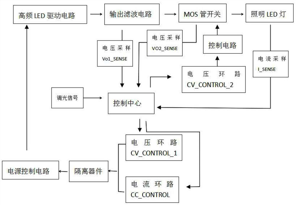
[0037] Disclosed in this embodiment as figure 1 A high-resolution LED dimming control circuit shown includes a control center, a high-frequency switching power supply LED drive circuit, a current sampling circuit and a control loop, a voltage sampling and a control loop, and a MOS tube switch. When the control circuit starts, If there is no load, it performs loop control on the LED drive of the high-frequency switching power supply according to the initial value preset by the control center, and outputs the constant voltage mode;
[0038]When the control circuit is not no-load, when the output current reaches the CC_REF value preset by the control, the constant current working mode is output;
[0039] When the external dimming signal is connected to DIMM_IN, the control circuit judges the dimming signal, selects the matching mode, and changes the output current by changing the value of the CC_CONTROL pin to realize dimming.
[0040] The control center includes analog / digital ...
Embodiment 2
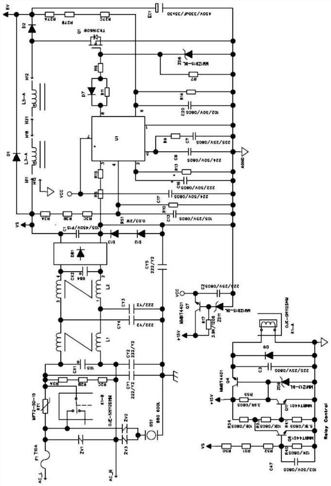
[0057] This embodiment discloses the first part of the high-resolution LED dimming control circuit, such as figure 2 The EMI filter circuit shown is composed of CX1, L1, L2, and CX2, which can reduce the CE interference of the power supply to the power grid, and the RE interference to the space, and improve the CS and RS interference immunity.
[0058] The rectification filter circuit is composed of DB1 and C1, which rectifies the input alternating current into direct current;
[0059] After being controlled by U1, L3-A, L5-A, D2, Q1, EC1 and their peripheral circuits, the input voltage is boosted to a constant voltage of 400V;
[0060] K1-B, K1-A circuits and their peripheral circuits, after the control power supply starts, the thermistor RT1 is short-circuited by the relay, which has improved the efficiency of the whole machine; the circuit samples the voltage at the input terminal through the capacitors R50, R51, R52, R40, and C47. When the input voltage drops or the mach...
Embodiment 3
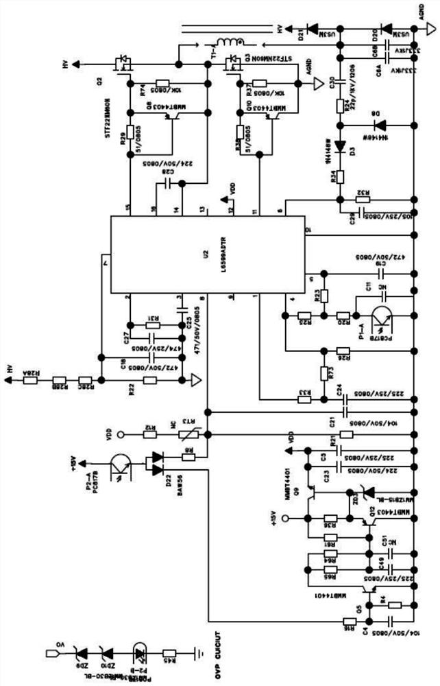
[0063] This embodiment discloses the second part of the high-resolution LED dimming control circuit, such as image 3 The LLC primary side power loop is composed of U2, Q2, Q3, T1, C6A, C6B and their peripheral circuits, and the MOS tube is in zero-voltage open state, which greatly reduces the switching loss of Q2 and Q3 and improves the whole machine. efficiency.
[0064] P1 is the secondary voltage and current sampling feedback closed-loop control optocoupler, and adjusts the operating frequency of the LLC circuit in real time according to the output load to achieve the purpose of stabilizing the output voltage.
[0065] P2 is the output overvoltage protection control optocoupler. When the output is overvoltage, the P2 transistor side is turned on, and the 15V voltage is limited and then poured into the 8 pin of the chip, and the VCC input of the chip is turned off, so that the chip turns off the output.
[0066] The second part of the circuit service control circuit works ...
PUM
 Abstract
Description
Claims
Application Information
 - R&D
- Intellectual Property
- Life Sciences
- Materials
- Tech Scout
- Unparalleled Data Quality
- Higher Quality Content
- 60% Fewer Hallucinations
Browse by: Latest US Patents, China's latest patents, Technical Efficacy Thesaurus, Application Domain, Technology Topic, Popular Technical Reports.
© 2025 PatSnap. All rights reserved.Legal|Privacy policy|Modern Slavery Act Transparency Statement|Sitemap|About US| Contact US: help@patsnap.com