Flexible magnetic flux sensor and manufacturing and mounting method thereof
A technology of a magnetic flux sensor and an installation method, which is applied to the magnetic measurement environment, measurement device, measurement of magnetic variables, etc., can solve the problems of troublesome operation, inconvenience to carry, complicated production, etc., and achieves easy investigation, easy portability and installation, and easy standardization Effect
- Summary
- Abstract
- Description
- Claims
- Application Information
AI Technical Summary
Problems solved by technology
Method used
Image
Examples
Embodiment 1
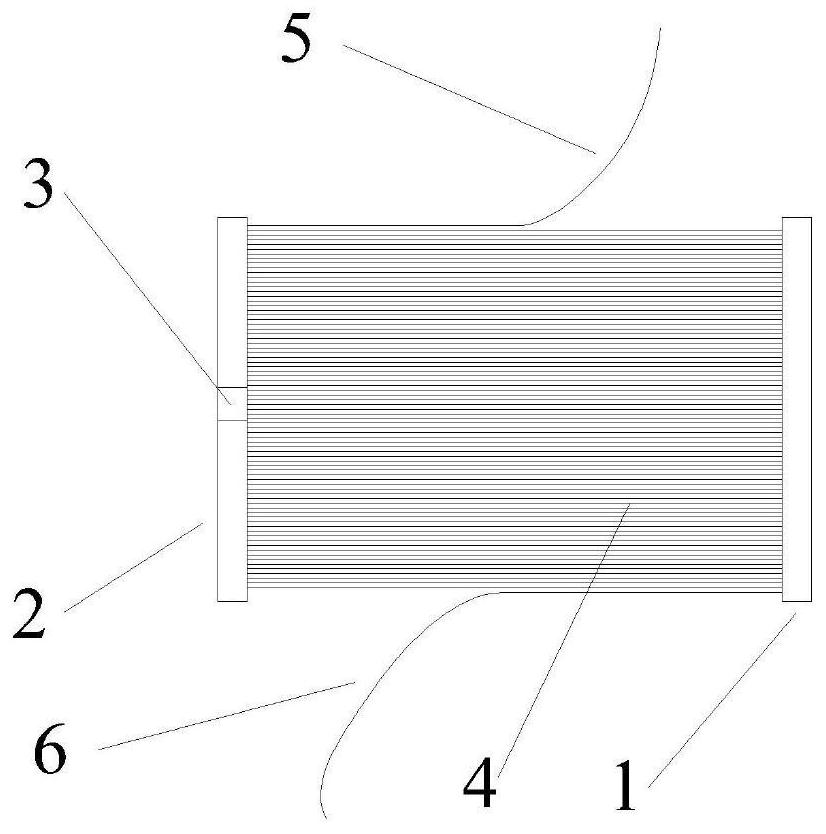
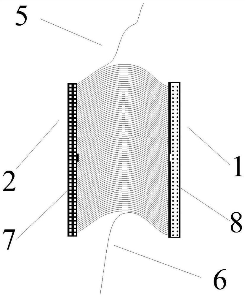
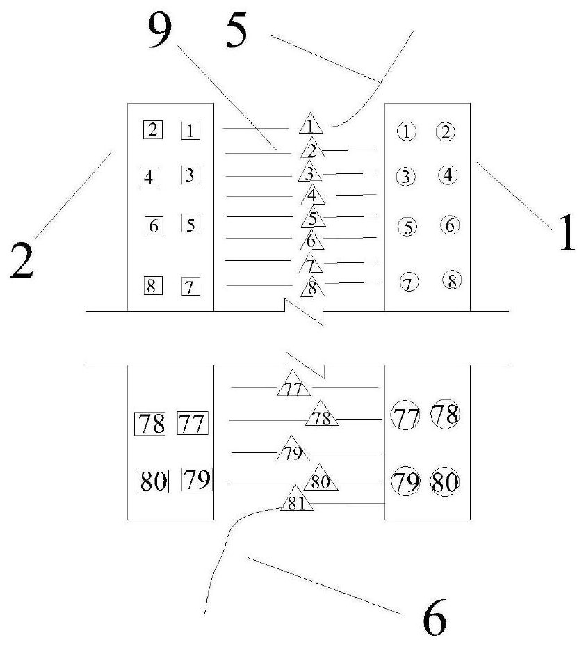
[0056] The magnetic flux sensor in this embodiment includes an excitation coil and an induction coil, and the selected shaping body is an air bag, which can be used for long-term monitoring. The schematic diagram of the sensor after installation is shown in Figure 10 . The diameter of the cable 26 is 116 mm, and the parameters of each component are designed with reference to the CCT120 magnetic flux sensor (inner diameter 120 mm, outer diameter 200 mm, height 350 mm) of Liuzhou OVM. figure 1 — Figure 4 It is a schematic diagram of the flexible coil assembly in the excitation coil. The flexible wire band 4 has 81 wires 9, the wires 9 are enameled wires with copper wires inside, and the wires 9 are wrapped in plastic; the production of the flexible wire band 4 adopts the production technology of IDE data lines . Respectively pull up a lead wire 9 at the two ends up and down, the upper end is the upper end lead wire 5, and the lower end is the lower end lead wire 6, like this...
Embodiment 2
[0061] This embodiment is a modification of Embodiment 1, and is used for short-term cable force measurement. The difference from Embodiment 1 is that the shaped body of the flexible coil assembly 21 is a thin plate made of soft rubber. Figure 11 Here is a schematic diagram of the end face of the connector of the flexible coil assembly 21. In order to ensure that the connection block 22 will not loosen by itself, two positioning cards 47 are designed on the outer side of the right connector 1. The schematic diagram is shown in the figure Figure 12 . Figure 13 It is a schematic diagram of the end face of the flexible coil-elastic gasket assembly, and the rubber gasket 41 is a shaped body. Figure 14 It is a schematic diagram of the upper end surface of the excitation coil 32. The main components of the excitation coil 32 include the first layer of flexible coil-elastic gasket assembly 42, the second layer of flexible coil-elastic gasket assembly 43, and the third layer of f...
Embodiment 3
[0063] This embodiment is an improved form of embodiment 2, Figure 16 Schematic diagram of the sensor after installation on site. The component for measuring the magnetic field strength in this embodiment is a magnetoelectric sensing element 48 extending out from a magnetic field strength signal line 49 . This makes the structure of the sensor more compact, uses standard electronic components, and improves the accuracy of the sensor. In order to avoid the interference of the surrounding magnetic field on the measurement results, a layer of aluminum foil strip 50 is wound on the outer surface of the excitation coil 32 .
PUM
| Property | Measurement | Unit |
|---|---|---|
| diameter | aaaaa | aaaaa |
| height | aaaaa | aaaaa |
Abstract
Description
Claims
Application Information
 - Generate Ideas
- Intellectual Property
- Life Sciences
- Materials
- Tech Scout
- Unparalleled Data Quality
- Higher Quality Content
- 60% Fewer Hallucinations
Browse by: Latest US Patents, China's latest patents, Technical Efficacy Thesaurus, Application Domain, Technology Topic, Popular Technical Reports.
© 2025 PatSnap. All rights reserved.Legal|Privacy policy|Modern Slavery Act Transparency Statement|Sitemap|About US| Contact US: help@patsnap.com


