
Railway tunnel air oscillation controller

A tunnel air and controller technology, applied in tunnels, mining equipment, earthwork drilling and mining, etc., can solve problems such as air vibration

Active Publication Date: 2020-10-27
温州泰乐维工程设计有限公司
View PDF9 Cites 3 Cited by
  • Summary
  • Abstract
  • Description
  • Claims
  • Application Information

AI Technical Summary

Problems solved by technology

[0003] In view of this, the object of the present invention is to provide a railway tunnel air vibration controller to solve the technical problem of air vibration caused by trains entering the tunnel

Method used


Image

  • Railway tunnel air oscillation controller
  • Railway tunnel air oscillation controller
  • Railway tunnel air oscillation controller

Examples


Embodiment

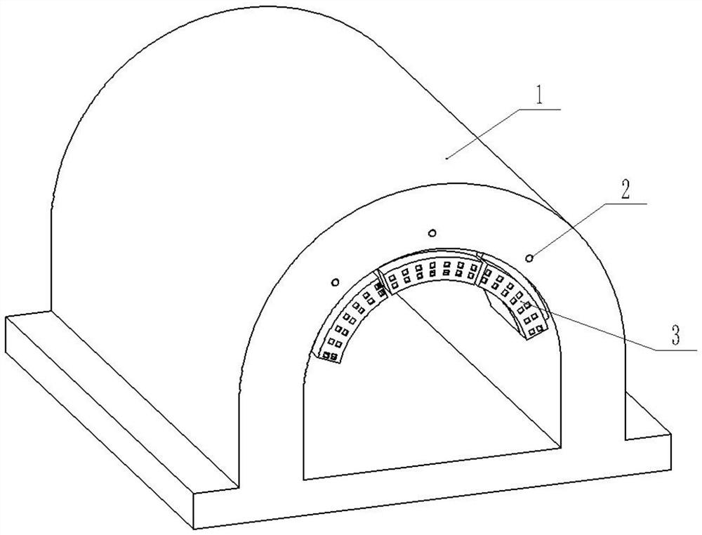
[0025] An air shock controller for railway tunnel 1, combined with figure 1 , including an arc-shaped control unit and a buffer piston arranged on the inner wall of the tunnel 1 .

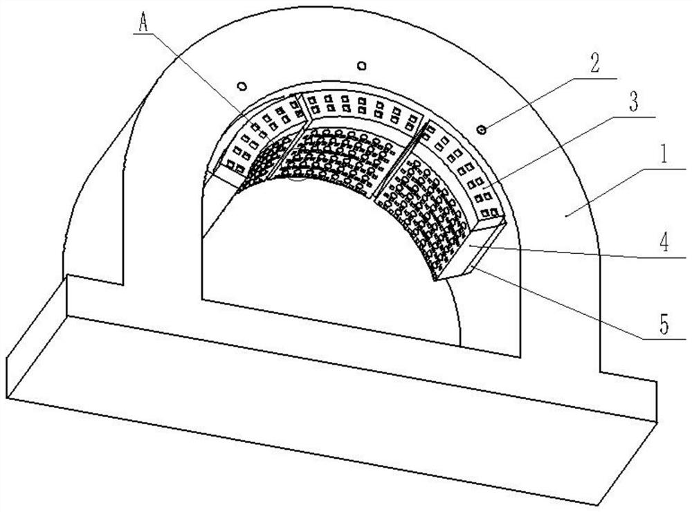
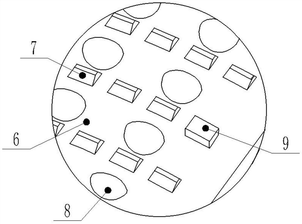
[0026] combine Figure 2-Figure 3 , the control unit includes an outer shell 4, the outer shell 4 is a frame shape with an open bottom, and the outer shell 4 is horizontally fixed with several layers of baffles 6, and each layer of baffles 6 is provided with a number of air inlets 7 and a number of buffer mechanisms . The air intake holes 7 in two adjacent partitions 6 are arranged alternately. The buffer mechanism includes a mounting groove 18, a first spring 19 and a buffer plate 8, the mounting groove 18 is arranged at the bottom of the partition plate 6, the first spring 19 is fixedly arranged in the mounting groove 18, and the buffer plate 8 is fixedly arranged on the first spring 19, The buffer sheets 8 are alternately arranged with the air intake holes 7, and the buffer sheets 8 are parti...


PUM


Abstract

The invention relates to the field of tunnels, and particularly discloses a railway tunnel air oscillation controller. The railway tunnel air oscillation controller comprises an arc-shaped control unit arranged on the inner wall of a tunnel; the control unit comprises an outer shell, a plurality of layers of partition plates are arranged in the outer shell, and a plurality of air inlet holes and aplurality of buffer mechanisms are arranged on each layer of partition plate; each buffer mechanism comprises a mounting groove, a first spring and buffer sheets; the mounting grooves are formed in the bottoms of the partition plates, the first springs are arranged in the mounting grooves, the buffer sheets are arranged on the first springs, the buffer sheets and the air inlet holes are alternately arranged, and the buffer sheets are partially spherical surfaces which are bent downwards; and a buffer cavity is formed between every two layers of partition plates, and a plurality of exhaust holes are formed in the two sides of the outer shell. The railway tunnel air oscillation controller aims to solve the technical problem of air oscillation caused when a train enters the tunnel.

Description

technical field [0001] The invention relates to the field of tunnels, and specifically discloses an air vibration controller for railway tunnels. Background technique [0002] Air vibration in railway tunnels means that when high-speed trains such as trains, high-speed trains or high-speed trains enter the railway tunnel, the train instantly squeezes the air at the tunnel entrance to form a high-pressure wave, which is reflected by the tunnel and then squeezes the train, so high-speed travel The train will produce a certain degree of vibration when it enters the tunnel mouth. This effect is called the piston effect. The existing high-speed trains in my country are basically high-speed trains. The speed of high-speed trains is generally 200-300km / h. When a high-speed train enters a tunnel at this speed, it will only produce relatively slight vibrations and will not have a negative impact on the running of the high-speed train. At present, my country is researching a high-spe...

Claims


Application Information

Patent Timeline
Patent Type & Authority Applications(China)
IPC IPC(8): F15D1/00E21D9/14
CPCE21D9/14F15D1/00
Inventor 刘玉峰
Owner 温州泰乐维工程设计有限公司
Learn More