A hydraulic power compensation balance valve

A compensation balance and hydraulic power technology, which is applied in the direction of fluid pressure actuators, servo motor components, mechanical equipment, etc., can solve the problems of many sealing points of balance valves, difficult processing, and increased leakage points, etc., to achieve load-flow Compensation, improvement of fretting performance, and less sealing points

Active Publication Date: 2022-05-17
JIANGSU ADVANCED CONSTR MASCH INNOVATION CENT LTD +1
View PDF7 Cites 0 Cited by
  • Summary
  • Abstract
  • Description
  • Claims
  • Application Information

AI Technical Summary

Problems solved by technology

[0004] The prior art has the following defects: (1) The existing balance valve with overcompensation function used in the hydraulic system of construction machinery is equipped with an overcompensation damping structure through the pilot valve core, which has complex structure, large volume and high cost;
[0005] (2) After the overcompensation function is added to the balance valve used in the hydraulic system of construction machinery, the balance valve has many sealing points, increases leakage points, and is difficult to process

Method used


Image

  • A hydraulic power compensation balance valve
  • A hydraulic power compensation balance valve
  • A hydraulic power compensation balance valve

Examples


Embodiment 1

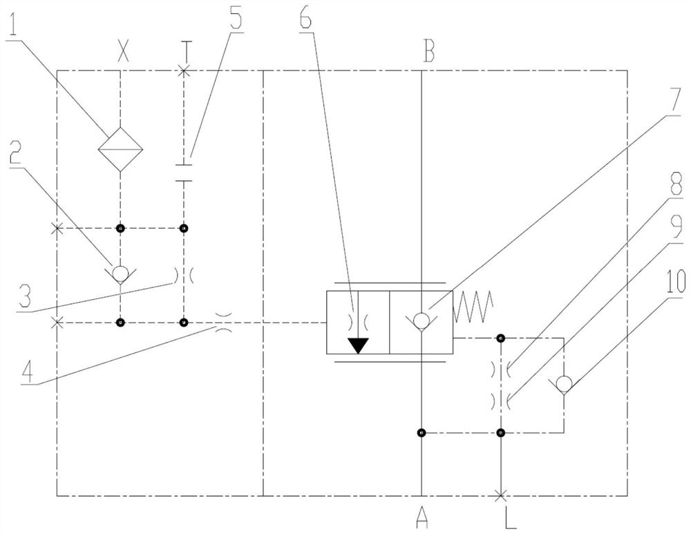
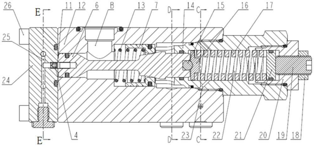
[0043] Such as figure 1 , figure 2 , image 3 As shown, a hydraulic power compensation balance valve includes: pilot control end cover assembly, balance valve body assembly, valve core assembly, one-way valve seat assembly;

[0044] The pilot control end cover assembly includes a control end cover valve body 24, which is provided with a pilot oil port X and a pilot oil passage 25; the spool assembly includes a throttle spool 6, a main spring 17, and a regulating valve seat 20 The one-way valve seat assembly includes a one-way valve 7 and one-way valve spring 13; the balance valve body assembly includes a balance valve body 12 and a valve seat 14, and the balance valve body 12 is provided with oil port B and oil port A, It is also provided with a valve core hole for installing the throttle valve core 6 and the check valve assembly;

[0045] The valve body 24 of the control end cover is fixed and sealed with the left end of the balance valve body 12, the valve seat 14 is fix...


PUM


Abstract

The invention discloses a hydraulic power compensation balance valve. The pilot control end cover assembly includes a control end cover valve body, and a pilot oil channel is arranged on the control end cover valve body; the valve core assembly includes a throttle valve core, a main spring, a regulating valve Seat; one-way valve seat assembly includes one-way valve and one-way valve spring; balance valve body assembly includes balance valve body and valve seat; throttle valve core is provided with a throttle port with an angle of α; the inner wall of the right end of the one-way valve The conical surface and the conical surface of the throttle port of the throttle spool cooperate with each other to form an openable seal; the one-way valve moves to the left during the luffing operation to realize the function of the one-way valve from the oil port A to the oil port B of the balance valve. During the luffing operation, the throttle spool opens to the right under the action of the pilot control pressure to realize the balance valve function from oil port B to oil port A, and as the load pressure increases, the angle through the throttle spool is α The hydraulic force generated during the annular flow channel controls the size of the throttle opening of the throttle spool to achieve load-flow compensation.

Description

technical field [0001] The invention belongs to the technical field of construction machinery and relates to a hydraulic power compensation balance valve. Background technique [0002] When the hydraulic system of construction machinery is working, if the load of the hydraulic cylinder is a vertical and horizontal load, and the direction of movement and gravity are consistent with the direction of the force, a balance valve must be used to generate oil flow resistance on the circuit to prevent the movement from losing control. Especially in the luffing system of the crane, the requirements for the balance valve are higher. The load moment arm increases due to the change of the luffing drop angle, and at the same time, the increase of the load pressure causes the luffing drop speed to become faster and faster, which is likely to cause safety accidents. Therefore, It is necessary to design a compensation function for the luffing balance valve that can effectively suppress the ...

Claims


Application Information

Patent Timeline
Patent Type & Authority Patents(China)
IPC IPC(8): F15B13/02
CPCF15B13/02F15B13/026
Inventor 翟亚楠苏丹枫程伟
Owner JIANGSU ADVANCED CONSTR MASCH INNOVATION CENT LTD
Why Eureka
Try Eureka