
Underwater concrete pouring device in steel pipe and concrete pouring method

A technology of underwater concrete and concrete, which is used in construction, infrastructure engineering, etc.

Active Publication Date: 2020-10-27
CHINA MCC5 GROUP CORP
View PDF4 Cites 3 Cited by
  • Summary
  • Abstract
  • Description
  • Claims
  • Application Information

AI Technical Summary

Problems solved by technology

[0003] The invention provides an underwater concrete pouring device and concrete pouring method in a steel pipe, aiming to solve the above-mentioned problems existing in the underwater concrete pouring device and concrete pouring method in a steel pipe in the prior art

Method used


Image

  • Underwater concrete pouring device in steel pipe and concrete pouring method
  • Underwater concrete pouring device in steel pipe and concrete pouring method

Examples


Embodiment 1

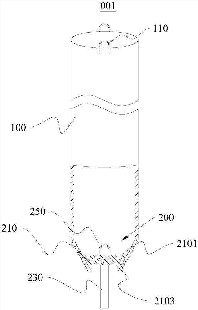
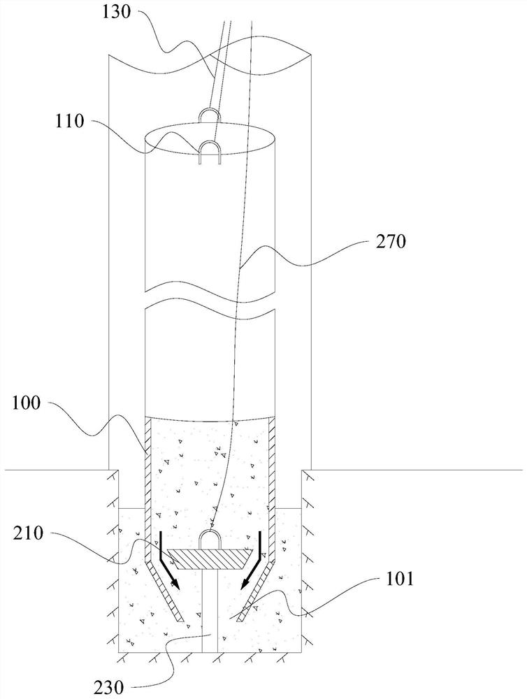
[0030] This embodiment provides an underwater concrete pouring device 001 in steel pipes, which is used for underwater concrete pouring in steel pipes for locking steel pipe pile cofferdams in deep water. Please refer to figure 1 and figure 2 , this underwater concrete pouring device 001 in a steel pipe includes a container pipe 100 and a plugging member 200;

[0031] The outer diameter of the container pipe 100 is slightly smaller than the inner diameter of the steel pipe of the deep-water locking steel pipe pile cofferdam, so that the container pipe 100 can extend into the steel pipe of the deep-water locking steel pipe pile cofferdam.

[0032] The container pipe 100 is used to accommodate the concrete that needs to be poured into the cofferdam of deep-water locking steel pipe piles. The bottom end of the container pipe 100 forms a constricted concrete outlet 101. When in use, the concrete in the container pipe 100 is discharged through the concrete outlet 101 .

[0033] ...

Embodiment 2

[0042] This embodiment provides a concrete pouring method, using the underwater concrete pouring device 001 in a steel pipe provided in Embodiment 1 to pour concrete, including steps:

[0043] Place the plug 200 into the bottom of the container pipe 100, and the steel rod 230 protrudes out of the concrete outlet 101;

[0044] The container pipe 100 is lowered into the steel pipe of the deep water locked steel pipe pile cofferdam through the second suspension rope 130;

[0045] The plugging member 200 descends following the container pipe 100 until it abuts against the bottom of the steel pipe of the deepwater locking steel pipe pile cofferdam;

[0046]The stopper 200 stops falling due to the abutment of the steel rod 230, and at the same time continues to lower the container tube 100, so that the seal of the tapered plate 210 fails;

[0047] The concrete outlet 101 of the container pipe 100 is opened, and the concrete in the container pipe 100 communicates with the concrete i...


PUM


Abstract

The invention provides an underwater concrete pouring device in a steel pipe and a concrete pouring method, and belongs to the field of concrete pouring. The underwater concrete pouring device is usedfor underwater concrete pouring of the steel pipe of a deep water lock catch steel pipe pile cofferdam and comprises a container pipe and a blocking part. A reduced concrete outlet is formed in one end of the container pipe. The blocking part comprises a conical plate, the conical plate is provided with a small end face and a large end face which are oppositely arranged, and the small end face ofthe conical plate faces the concrete outlet and is used for blocking the concrete outlet. The small end face is further fixedly provided with a steel bar stretching out of the concrete outlet. By means of the underwater concrete pouring method in the steel pipe, the problem that an existing conventional underwater concrete pouring process cannot be suitable for concrete pouring in the small-aperture steel pipe pile of the deep water lock catch steel pipe pile cofferdam can be solved. The underwater concrete pouring device in the steel pipe is simple in structure, easy to machine, convenient to construct and operate and reliable in pouring quality, and the problem that the conventional process cannot be suitable for underwater concrete pouring is ingeniously solved.

Description

technical field [0001] The invention relates to the field of concrete pouring, in particular to an underwater concrete pouring device in a steel pipe and a concrete pouring method. Background technique [0002] The locking steel pipe pile cofferdam used in the construction of deep water foundation caps of bridges is composed of a single steel pipe pile unit. It is connected with the unit through I-beam and slotted steel pipe, which has the advantages of mature processing technology, simple construction method, and accelerated construction period. When this form of cofferdam is used in silt layer, clay layer, and silt layer geological riverbed, it can be directly driven to the design elevation by using a vibratory hammer. However, when it is applied to the river bed composed of dense sandy pebble layer and mudstone layer, it is necessary to drill the pilot hole in the steel pipe so that the steel pipe pile can be inserted to the top of the bedrock, but it is very difficult t...

Claims


Application Information

Patent Timeline
IPC IPC(8): E02D15/04
CPCE02D15/04
Inventor 文常娟王渊张泽明苏炳建
Owner CHINA MCC5 GROUP CORP
Learn More