Intelligent grouting equipment and pile foundation construction method

An intelligent and equipment-based technology, applied in infrastructure engineering, sheet pile walls, buildings, etc., can solve problems such as difficulty in moving the grouting machine, dispersion, and inability to guarantee the quality of grouting

Pending Publication Date: 2020-10-27
CHINA RAILWAY FIFTH SURVEY & DESIGN INST GRP
View PDF0 Cites 2 Cited by
  • Summary
  • Abstract
  • Description
  • Claims
  • Application Information

AI Technical Summary

Problems solved by technology

[0003] The embodiment of the present application provides an intelligent grouting equipment and a pile foundation construction method. The intelligent grouting equipment is integrated with a pulping machine, a grouting machine and a control device on a mobile trolley, which can solve the problem of exi...

Method used


Image

  • Intelligent grouting equipment and pile foundation construction method
  • Intelligent grouting equipment and pile foundation construction method
  • Intelligent grouting equipment and pile foundation construction method

Examples


Embodiment 1

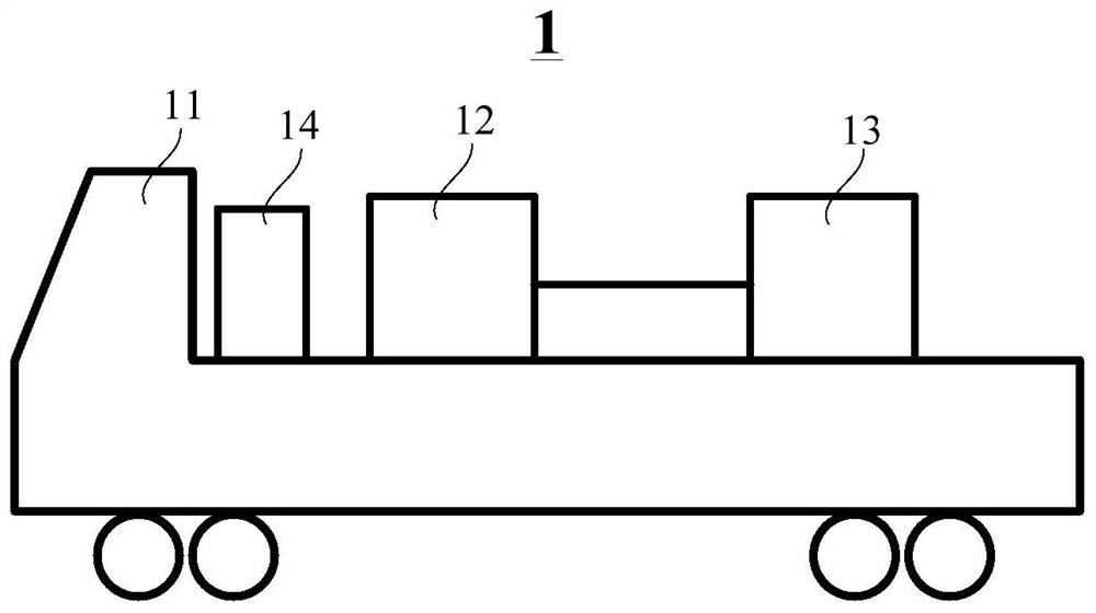
[0043] like figure 1 , figure 2 and image 3 As shown in the structure, the embodiment of the present application provides an intelligent grouting equipment 1, the intelligent grouting equipment 1 includes a mobile trolley 11, a pulping machine 12, a pulping machine 13 and a control device 14;

[0044] Mobile trolley 11 comprises car body; As figure 1 As shown in the structure, the mobile trolley 11 includes a car body, and the bottom of the car body is provided with wheels. The mobile trolley 11 can also include a power system such as a driving device (not shown) installed on the car body, and a power system such as a driving device Used to generate driving force and drive the car body to move; the mobile trolley 11 can be driven by its own power system to change its position, or can be driven by an external power source such as a tractor to move the car body;

[0045] Pulp making machine 12 is removably installed on mobile trolley 11, is used for preparing cement slurry;...

Embodiment 2

[0059] The embodiment of the present application also provides a pile foundation construction method using any one of the intelligent grouting equipment 1 in the above embodiments for grouting, such as Figure 4 shown, including the following steps:

[0060] Step S10, drill hole 2; drill hole 2 by a drilling rig at the position where the pile foundation needs to be set;

[0061] Step S20, arranging the reinforcement cage 3 and the grouting pipe 4 into the drilled hole 2; the reinforcement cage 3 can be a prefabricated part, or made on site;

[0062] Step S30, clearing the hole 2;

[0063] Step S40, setting the water-cement ratio of the pulper 12;

[0064] Step S50, connecting the pulp outlet of the pulp press 13 of the intelligent pulping equipment 1 with the inlet of the pulping pipe 4;

[0065] Step S60, using the pulping machine 12 of the intelligent grouting equipment 1 for pulping to form cement slurry;

[0066] In step S70, the cement slurry prepared by the pulping m...


PUM


Abstract

The embodiment of the invention relates to the technical field of civil construction, in particular to intelligent grouting equipment and a pile foundation construction method. The intelligent grouting equipment comprises a movable trolley, a slurry making machine, a grouting machine and a control device; the movable trolley comprises a trolley body; the slurry making machine is detachably installed on the movable trolley and is used for preparing cement slurry; the grouting machine is detachably installed on the movable trolley, a grout inlet of the grouting machine is in communication with adischarge port of the slurry making machine, and the grouting machine is used for conveying the cement slurry prepared by the slurry making machine; and the control device is used for controlling theslurry making machine and the grouting machine to work. The intelligent grouting equipment can solve the problems that existing grouting equipment is disorderly and dispersedly placed and stored andneeds to be manually controlled, the grouting quality cannot be guaranteed due to the influence of human factors and the environment, and the grouting machine is difficult to move when the pile foundation distance is large.

Description

technical field [0001] The present application relates to the technical field of civil engineering, in particular to an intelligent grouting equipment and a pile foundation construction method. Background technique [0002] With the development of infrastructure, post-grouting technology has been gradually promoted and flourished in construction, transportation construction and other fields. However, the traditional grouting machine and pulping machine currently used are set independently, and they need to be controlled and installed separately during use, resulting in messy and scattered placement and storage, requiring human control, and the quality of grouting is easily affected by human factors, environmental factors It cannot be guaranteed due to the impact of the impact, and it is difficult for the grouting machine to move when the pile foundation is far away. SUMMARY OF THE INVENTION [0003] The embodiment of the present application provides an intelligent groutin...

Claims


Application Information

Patent Timeline
IPC IPC(8): E02D15/04E02D5/34
CPCE02D5/34E02D15/04
Inventor 桂婞李彬汤友富王永国罗九林郭亚娟张润泽
Owner CHINA RAILWAY FIFTH SURVEY & DESIGN INST GRP
Why Eureka
Try Eureka