
Soil remediation device

A technology of soil remediation and fluvo-aquic soil, which is applied in the field of soil remediation, and can solve problems such as erosion loss of deep soil on the surface, water loss inside the soil, soil damage, etc.

Active Publication Date: 2020-10-27
青岛博弘环境科技有限公司
View PDF9 Cites 1 Cited by
  • Summary
  • Abstract
  • Description
  • Claims
  • Application Information

AI Technical Summary

Problems solved by technology

[0005] In order to overcome the large amount of sand in the river due to the water flow movement of the river, some sand fields are often opened in some river areas, but because the sand is often concentrated and the quality of the sand is relatively light, most of it is distributed above the inner rocks on the surface, that is, in the The surface part, so most of the sand is collected by digging down from the surface. During the excavation and collection process, obstacles such as large rocks and other obstacles that appear during the excavation process will be manually removed from the sand pit, which in turn leads to After the sand is excavated, there is no residual sand inside the bunker, and the deep soil on the surface is exposed. At the same time, the large rocks inside it are separated, causing the deep soil on the surface to be directly exposed to the surface. The sand pit is washed by water again, which will cause the deep soil on the surface to be further washed away. Loss, the internal moisture of the soil near the bunker is lost, the vegetation on the surface cannot continue to absorb water, and the ecology is destroyed. At the same time, due to the erosion of rainwater and water flow, the bunker will continue to expand. Destruction, the shortcoming that the surface ecosystem is destroyed in a large area, the technical problem of the present invention: provide a kind of soil remediation device

Method used


Image

  • Soil remediation device
  • Soil remediation device
  • Soil remediation device

Examples


Embodiment 1

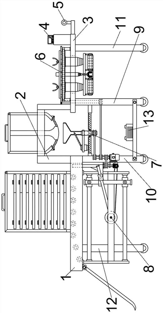
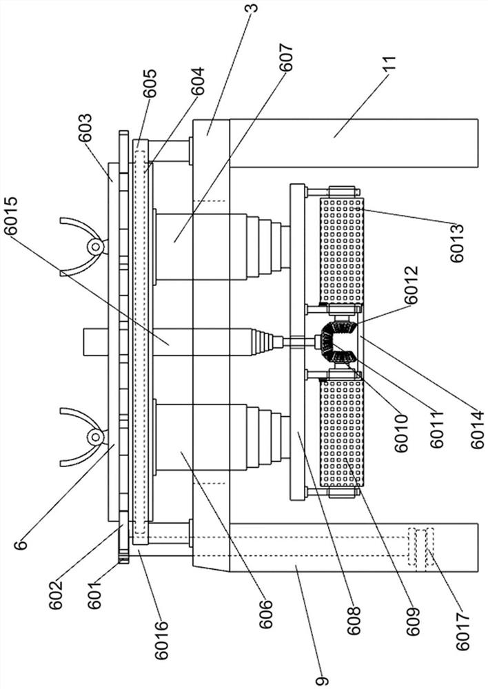
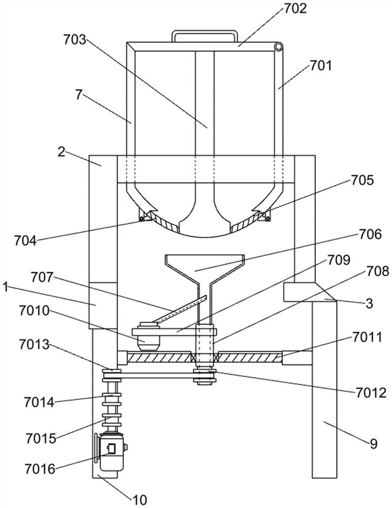
[0028] A soil remediation device such as Figure 1-6 As shown, it includes a U-shaped frame plate 1, a first frame plate 2, a second frame plate 3, an operation control panel 4, a manual assisted push handle 5, a mechanism for leveling the bottom moisture soil 6, a filling mechanism 7, and a stone plate Operation and amplifier mechanism 8, the first power wheel foot frame 9, the second power wheel foot frame 10, the third power wheel foot frame 11, the fourth power wheel foot frame 12 and the energy storage battery 13; U-shaped frame plate 1 and the first The frame plate 2 is connected by bolts; one side below the U-shaped frame plate 1 is connected with the second power wheel foot frame 10, and the other side below the U-shaped frame plate 1 is connected with the fourth power wheel foot frame 12; the first The frame plate 2 is bolted to the second frame plate 3; the bottom of the second frame plate 3 is sequentially connected with the first power wheel foot frame 9 and the th...


PUM


Abstract

The invention relates to the field of soil remediation, in particular to a soil remediation device. In order to solve technical problems in the prior art, the soil remediation device is provided. According to the technical scheme, the soil remediation device comprises a manual auxiliary pushing handle, a bottom-layer moisture soil spreading mechanism, a filling mechanism, a slabstone conveying-placing mechanism and the like, wherein a first power wheel stand and a third power wheel stand are sequentially connected with the lower part of a second rack plate. Through the soil remediation device,the layered landfill remediation of a sandpit is achieved; and specifically, moisture soil is uniformly spread on the bottom layer of the sandpit for bottom trough formation at first, the foundationof the sandpit is stabilized, the moisture soil is tightly combined with the side wall of the sandpit, the landfill operation on the sandpit is performed by using sand and stone which have the same soil quality as the surrounding environment, the sandpit subjected to the landfill operation is compacted by large slabstone for a long time, the soil quality of the sandpit is compressed and solidified, the remediation of the sandpit is completed, and the effect of preventing water and soil loss as well as protecting ecology is achieved.

Description

technical field [0001] The invention relates to the field of soil restoration, in particular to a soil restoration device. Background technique [0002] Soil remediation is a technical measure to restore the normal function of polluted soil. In the soil remediation industry, there are more than one hundred existing soil remediation technologies, and there are more than ten commonly used technologies, which can be roughly divided into three methods: physical, chemical and biological. Since the 1980s, many countries in the world, especially developed countries, have formulated and carried out plans for the treatment and restoration of contaminated soil, thus forming a new soil restoration industry. [0003] At present, sand is a commonly used building material in the construction field. In the prior art, the water flow of the river causes a large amount of sand in the river, and some sand fields are often set up in some river areas, but because the sand is often concentrated ...

Claims


Application Information

Patent Timeline
IPC IPC(8): E02D3/00
CPCE02D3/00
Inventor 张波
Owner 青岛博弘环境科技有限公司
Learn More