
Roadbed drainage structure

A technology of drainage structure and roadbed, applied in the direction of road bottom, buildings, etc., can solve problems such as the falling off of drainage mechanism, the influence of roadbed drainage, and the loosening of drainage structure.

Inactive Publication Date: 2020-10-27
岳阳智博建筑工程有限公司
View PDF9 Cites 0 Cited by
  • Summary
  • Abstract
  • Description
  • Claims
  • Application Information

AI Technical Summary

Problems solved by technology

A subgrade drainage structure in the above-mentioned patent has the following disadvantages: when the existing drainage structure is draining, the drainage structure may be loosened due to the impact of water flow, which will cause the drainage mechanism to fall off the subgrade, thereby causing serious damage to the drainage of the subgrade. influences

Method used


Image

  • Roadbed drainage structure
  • Roadbed drainage structure
  • Roadbed drainage structure

Examples


Embodiment 1

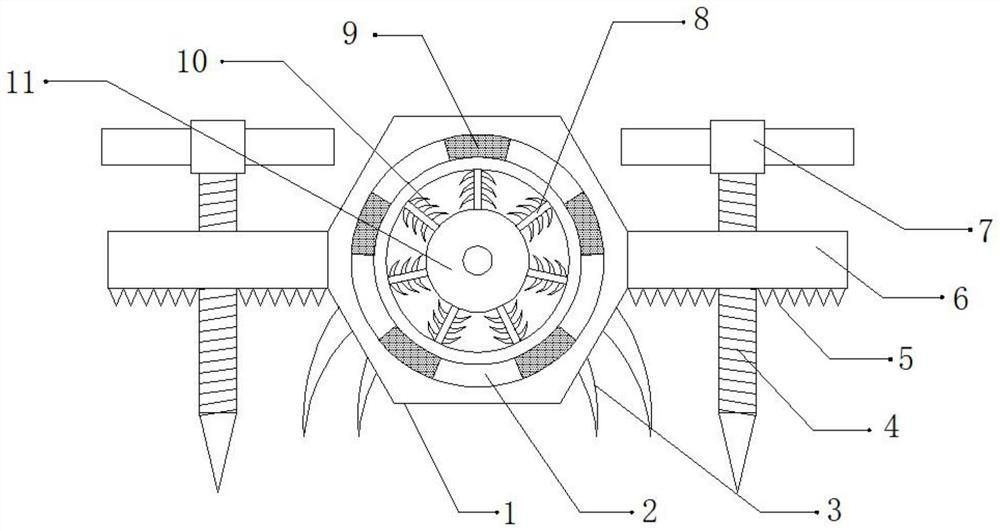
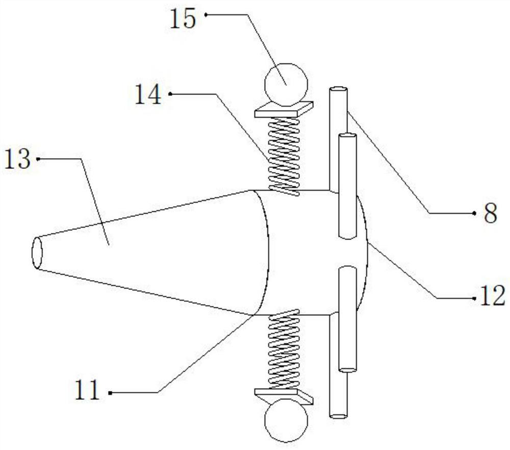
[0024] refer to Figure 1-2 , a subgrade drainage structure, comprising a fixed plate 1, the outer walls of both sides of the fixed plate 1 are connected with fixed blocks 6 by bolts, and the top outer walls of the two fixed blocks 6 are provided with threaded holes, and the inner walls of the two threaded holes are Threaded rods 4 are threaded, and the bottom outer walls of the two threaded rods 4 are connected with plug-in blocks by bolts, the top outer walls of the two threaded rods 4 are connected with turning handles 7 by bolts, and the bottom outer walls of the two fixed blocks 6 are connected by bolts. There are a plurality of tooth blocks 5 equidistantly distributed, the outer walls on both sides of the fixed plate 1 are connected with a plurality of barbs 3 by bolts, and the shape of the barbs 3 is arc-shaped, and the outer wall on one side of the fixed plate 1 is provided with drainage Mouth 2.

[0025] Wherein, the inner wall of the drain port 2 is connected with a...

Embodiment 2

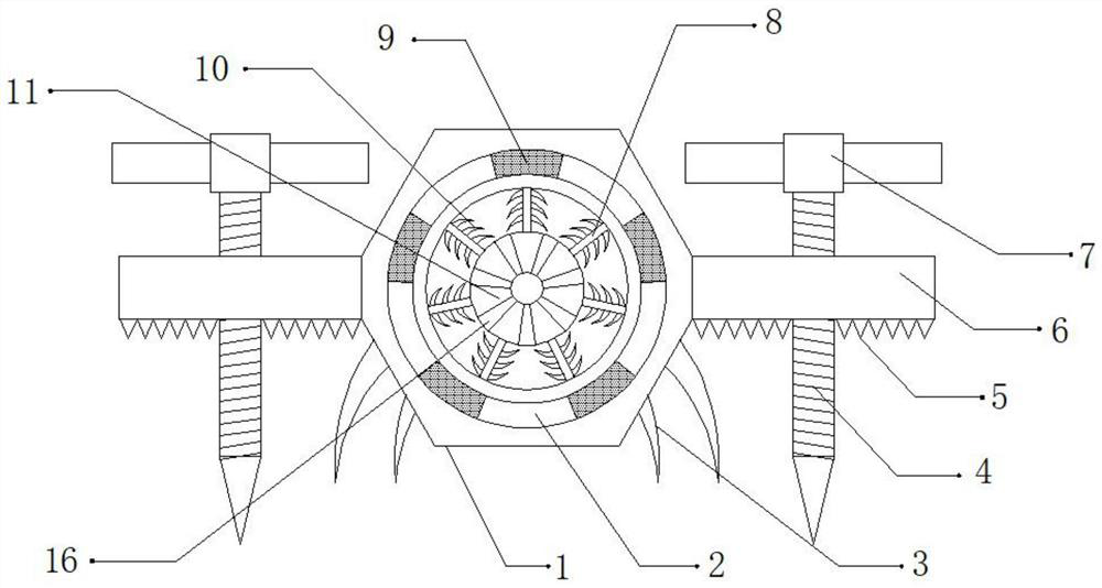
[0028] refer to image 3 , a subgrade drainage structure. Compared with Embodiment 1, the outer wall of the diverter block 13 is provided with a plurality of diversion grooves 16, and the cross-section of the diversion grooves 16 is tapered, which can slow down the flow velocity of the water. In order to facilitate the drainage treatment of the roadbed.

[0029] Working principle: When in use, install the drainage structure on the roadbed, twist and turn 7, so that the threaded rod 4 drives the insert block to move downward, and then fix the drainage structure on the roadbed, through the tooth block 5 and the barb 3 can increase The friction between the large drainage structure and the roadbed is convenient for installing and fixing the drainage structure, preventing the drainage structure from falling off the roadbed due to the impact of flowing water, thereby affecting the drainage of the roadbed, and the flowing water will be diverted through the diversion mechanism 11 tre...


PUM


Abstract

The invention discloses a roadbed drainage structure, which comprises afixing plate.Fixing blocks are fixedly connected to the outer walls of the two sides of the fixing plate. Threaded holes are formed in the outer walls of the tops of the two fixingblocks; threaded rods are in threaded connection with the inner walls of the two threaded holes; inserting blocks are fixedly connected to the outerwalls of the bottoms of the two threaded rods correspondingly, rotating handles are fixedly connected to the outer walls of the tops of the two threaded rods correspondingly, a plurality of tooth blocks distributed at equal intervals are arranged on the outer walls of the bottoms of the two fixing blocks correspondingly, a plurality of barbs are fixedly connected to the outer walls of the two sides of the fixing plate correspondingly, and the barbs are in an arc shape. The drainage structure can be prevented from falling off from the roadbed due to the impact force of flowing water, the situation that the impact force borne by the drainage structure is large to affect drainage of the roadbed due to the fact that the water flow is gathered together due to the high speed of the water flow can be prevented, and the situation that the interior of the drainage structure is blocked due to the large size of impurities can be prevented.

Description

technical field [0001] The invention relates to the field of roadbed technology, in particular to a roadbed drainage structure. Background technique [0002] Due to the needs of drainage, drainage structures are usually required in the roadbed to facilitate the drainage of water. [0003] After searching, the Chinese patent authorization number is CN209339018U, which discloses a subgrade drainage structure, including a pipe body and a fixing part, and the fixing part includes a fixing plate, a guide sleeve and a positioning rod, and the fixing plate and the pipe body The side part of the fixed plate is connected with a first through hole, the guide sleeve is fixed on the fixed plate and communicated with the first through hole, and the positioning rod passes through the first through hole in turn. Holes and guide sleeves, and a plurality of fixing pieces are symmetrically arranged on the side of the pipe body in two rows. Compared with the prior art, the present invention ...

Claims


Application Information

Patent Timeline
IPC IPC(8): E01F5/00
CPCE01F5/00
Inventor 罗胜利
Owner 岳阳智博建筑工程有限公司
Learn More