A graphite rod slice processing graphite gasket equipment
A graphite pad and graphite rod technology, applied in stone processing equipment, stone processing tools, work accessories, etc., to achieve the effect of consistent thickness, reduced labor intensity, and easy collection
- Summary
- Abstract
- Description
- Claims
- Application Information
AI Technical Summary
Problems solved by technology
Method used
Image
Examples
Embodiment 1
[0025] A graphite rod slice processing graphite gasket equipment, such as Figure 1-3 As shown, it includes a support plate 1, an operation plate 2, a storage plate 3, a mounting plate 4 and a cutting mechanism 5, the left and right sides of the bottom of the operation plate 2 are connected with the support plate 1, and the right side of the operation plate 2 rear side is connected with a The storage board 3 and the right side of the top of the operation board 2 are connected with an installation board 4 , and a cutting mechanism 5 is installed between the operation board 2 , the storage board 3 and the installation board 4 .
[0026] The cutting mechanism 5 includes an L-shaped connecting plate 51, a feeding pipe 52, a servo motor 53, a sprocket drive group 54, a slider 55, a first connecting plate 56, a second connecting plate 57, a first telescopic rod 58, a first Spring 59, inclined head block 510, limit slideway 511, the third connecting plate 512, blade 513, material ret...
Embodiment 2
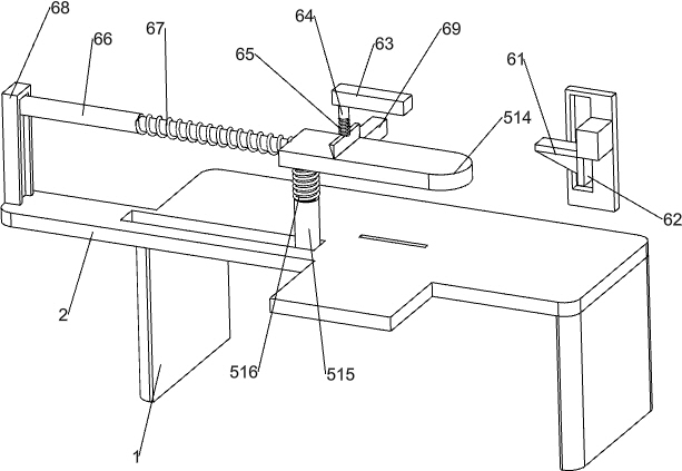
[0029] On the basis of Example 1, such as figure 1 and Figure 4As shown, it also includes a stopper mechanism 6, and the stopper mechanism 6 includes a first wedge block 61, a baffle plate 62, a fourth connecting plate 63, a third telescopic rod 64, a third spring 65, a fourth telescopic rod 66, The fourth spring 67, slotted connecting plate 68 and the fifth connecting plate 69, the left side of the second connecting plate 57 is connected with the first wedge-shaped block 61, the right side of the first wedge-shaped block 61 is connected with the baffle plate 62, and the feeding pipe 52 The left side is connected with the fourth connecting plate 63, the left side of the fourth connecting plate 63 bottom is connected with the third telescopic rod 64, the telescopic end of the third telescopic rod 64 is connected with a push plate, and the push plate is connected with the third telescopic rod 64. The third spring 65 is arranged, and the top of the operation plate 2 on the left...
Embodiment 3
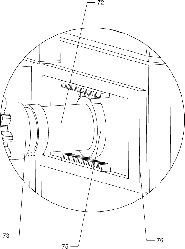
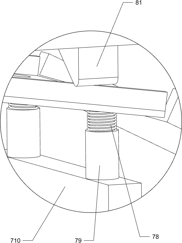
[0032] On the basis of Example 2, such as figure 1 and Figure 5-7 As shown, it also includes a dust removal mechanism 7, and the dust removal mechanism 7 includes a rack plate 71, a transmission rod 72, a one-way clutch 73, a transmission gear 74, a half gear 75, a rack frame 76, a screening frame 77, a fifth Spring 78, the fifth telescopic rod 79, the sixth connecting plate 710 and the seventh connecting plate 711, the bottom of the fifth connecting plate 69 is connected with a rack plate 71, and the operation plate 2 on the front side of the limit slideway 511 is rotatably connected with Transmission rod 72, the rear side of transmission rod 72 is connected with one-way clutch 73, is connected with transmission gear 74 on the one-way clutch 73, and transmission gear 74 meshes with rack plate 71, and transmission rod 72 front side is connected with half gear 75, and transmission rod 72 The top of the operation plate 2 on the front side is slidingly connected with the sevent...
PUM
 Abstract
Description
Claims
Application Information
 - Generate Ideas
- Intellectual Property
- Life Sciences
- Materials
- Tech Scout
- Unparalleled Data Quality
- Higher Quality Content
- 60% Fewer Hallucinations
Browse by: Latest US Patents, China's latest patents, Technical Efficacy Thesaurus, Application Domain, Technology Topic, Popular Technical Reports.
© 2025 PatSnap. All rights reserved.Legal|Privacy policy|Modern Slavery Act Transparency Statement|Sitemap|About US| Contact US: help@patsnap.com


