Integrated prefabricated part module and mold device and use method
A technology of prefabricated components and molds, which is applied in the field of housing construction, and can solve problems such as the inability to calibrate the two-layer steel mesh, the offset of the steel mesh on both sides, and the addition of steel bars.
- Summary
- Abstract
- Description
- Claims
- Application Information
AI Technical Summary
Problems solved by technology
Method used
Image
Examples
Embodiment 1
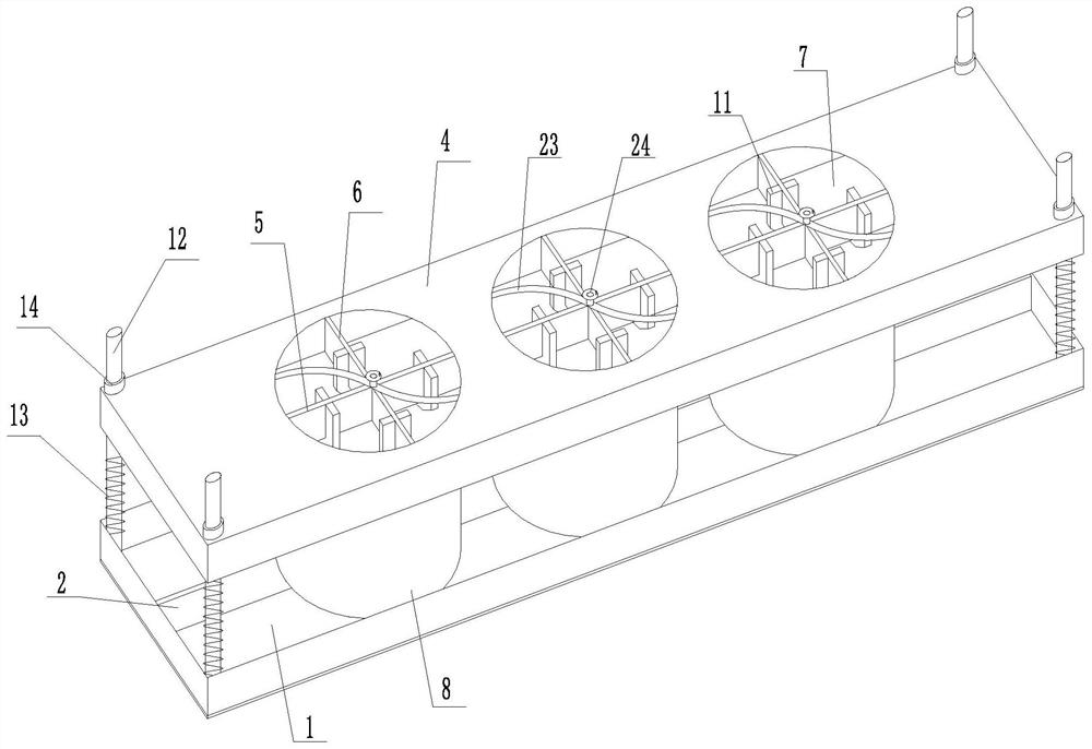
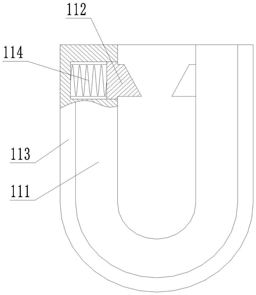
[0029] like figure 1 , image 3 and Figure 4 As shown, the integrated prefabricated component module mold device includes a bottom formwork, a top formwork, a side formwork 8 and a connecting unit. The bottom formwork includes a bottom plate 1, a first partition 2 and a second partition 3. The side panels are fixedly connected, and the first partition 2 and the second partition 3 are vertically intersected and fixedly connected to the bottom plate 1, wherein the first partition 2 is fixed horizontally, and the three second partitions 3 are fixed vertically. 2 and the two ends of the second partition 3 are respectively fixedly connected with the corresponding side plates, the top template includes a top plate 4, a third partition 5 and a fourth partition 6, the top plate 4 is provided with a through hole 7, and the third partition 5 and the fourth partition 6 are vertically intersected on the top plate 4, the intersecting points of the third partition 5 and the fourth partit...
Embodiment 2
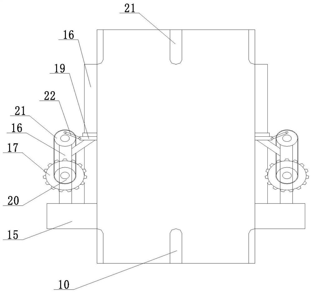
[0034] Such as figure 2 As shown, different from Embodiment 1, the side template 8 is provided with a vibrating structure, and the vibrating structure includes a moving ring 15, a fixed frame 16, a gear 17, a transmission assembly, a rack 18 and a vibrating rod 19, and the moving ring 15 is arranged on On the outside of the side template 8, the fixed frame 16 is fixedly connected on the moving ring 15, the gear 17 is rotated and arranged on the fixed frame 16, the gear 17 is connected with the vibrating rod 19 through the transmission assembly, and the rack 18 is fixedly arranged on the side template 8 and is connected to the side template 8. The gears 17 are meshed, the vibrating rod 19 is slidably connected to the fixing part, and the moving direction of the vibrating rod 19 is perpendicular to the side template 8 . The transmission assembly includes a driving part 20, a driven part 21 and a connecting rod 22. The driving part 20 is coaxially fixed on the gear 17, the drive...
Embodiment 3
[0036] Such as figure 1 As shown, different from Embodiment 2, the top formwork also includes a rotating shaft 24, the rotating shaft 24 is arranged at the intersection of the third partition 5 and the fourth partition 6, and the rotating shaft 24 is fixedly connected with the through hole 7 The matching scraper 23 is in the shape of an arc blade. Use the rotating shaft 24 to drive the scraper 23 matched with the through hole 7 to scrape the top of the vibrated slurry (excess scraping, a small amount of filling), to further ensure the quality of its pouring and prevent pitting from affecting its use.
PUM
 Abstract
Description
Claims
Application Information
 - R&D Engineer
- R&D Manager
- IP Professional
- Industry Leading Data Capabilities
- Powerful AI technology
- Patent DNA Extraction
Browse by: Latest US Patents, China's latest patents, Technical Efficacy Thesaurus, Application Domain, Technology Topic, Popular Technical Reports.
© 2024 PatSnap. All rights reserved.Legal|Privacy policy|Modern Slavery Act Transparency Statement|Sitemap|About US| Contact US: help@patsnap.com


