Eureka AIR delivers breakthrough ideas for toughest innovation challenges, trusted by R&D personnel around the world.
A special boring machine for multifunctional mechanical processing
What is Al technical title?
Al technical title is built by PatSnap Al team. It summarizes the technical point description of the patent document.
A mechanical processing and multi-functional technology, applied in the direction of metal processing equipment, metal processing machinery parts, manufacturing tools, etc., can solve the problems of inconvenient left and right movement, inconvenient overall hoisting work of lighting equipment, inconvenient blocking work, etc.
Active Publication Date: 2022-03-11
HELI TECH ENERGY CO LTD
View PDF0 Cites 0 Cited by
Summary
Abstract
Description
Claims
Application Information
AI Technical Summary
This helps you quickly interpret patents by identifying the three key elements:
Problems solved by technology
Method used
Benefits of technology
Problems solved by technology
[0005] In order to solve the above-mentioned technical problems, the present invention provides a multi-functional boring machine dedicated to mechanical processing, to solve the problem that the existing boring machine is inconvenient to perform shielding work during use, and it is inconvenient to move lighting equipment left and right during work and inconvenient In the process of installation and movement, it is inconvenient to carry out overall hoisting work and it is convenient to protect the equipment during use
Method used
Image
Click on the blue label to locate the original text in one second.
Reading with bidirectional positioning of images and text.
Examples
Embodiment Construction
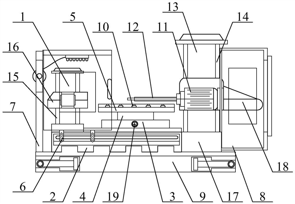
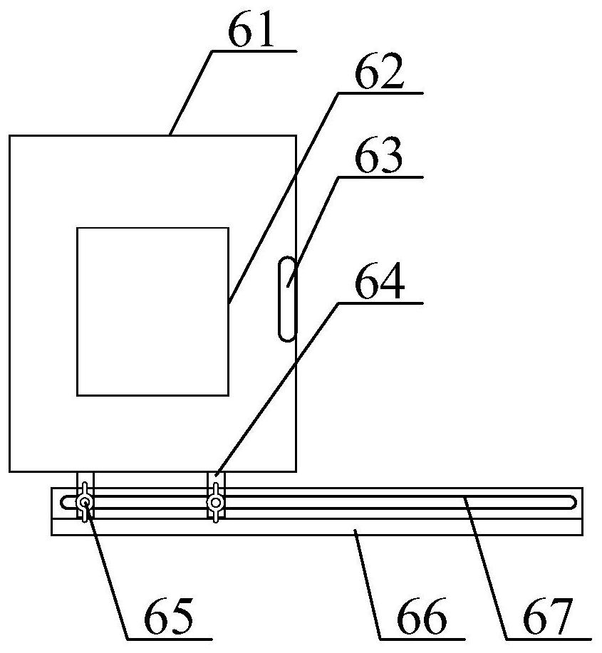
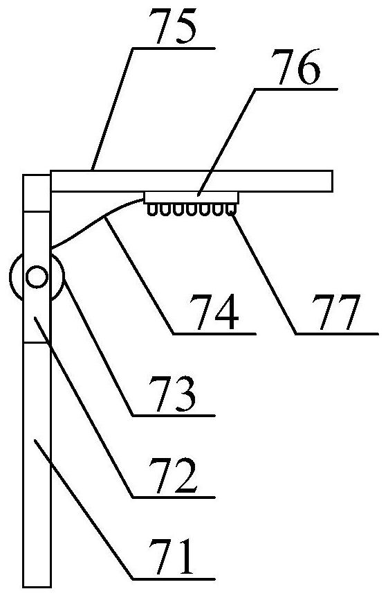
[0035] The present invention is described in detail below in conjunction with accompanying drawing, as appended figure 1 And attached figure 2As shown, a multifunctional boring machine dedicated to mechanical processing includes a rear column 1, a boring machine bed 2, a working base 3, a turntable 4, a workbench 5, a sliding and locking cover structure 6, and a retractable and absorbing lighting seat Structure 7, Observable protective maintenance cover structure 8, retractable lifting seat structure 9, faceplate 10, motor 11, boring shaft body 12, front column 13, first guide rail 14, second guide rail 15, tailstock 16, connecting seat 17. Boring shaft rear seat 18 and control valve 19. The rear column 1 is bolted to the left side of the upper end of the boring machine bed 2; the working base 3 is bolted to the middle position of the upper end of the boring machine bed 2; The workbench 5 is set in rotational connection with the work base 3 through the turntable 4; the slida...
PUM
Abstract
The invention provides a multifunctional boring machine dedicated to mechanical processing, which includes a rear column, a boring machine bed, a working base, a turntable, a worktable, a sliding and locking cover structure, a retractable adsorption lighting seat structure, and observation, protection and maintenance. Cover structure, retractable lifting seat structure, faceplate, motor, boring shaft body, front column, first guide rail, second guide rail, tailstock, connecting seat, boring shaft rear seat and control valve, the rear column bolt connection On the left side of the upper end of the boring machine bed; the working base bolts are connected to the middle position of the upper end of the boring machine bed. The setting of the shielding cover, tempered glass sheet, push rod, sliding rod, U-shaped seat and boring machine bed of the present invention is beneficial to grasp the push rod to push the shielding cover to move to the upper end of the boring machine bed in the process of processing workpieces, which is convenient to install on the boring machine bed. Cover work during work to prevent debris generated during work from polluting the working environment.
Description
technical field [0001] The invention belongs to the technical field of boring machine equipment, and in particular relates to a multifunctional boring machine dedicated for mechanical processing. Background technique [0002] A boring machine is a machine tool that mainly uses a boring tool to bore the existing prefabricated holes of the workpiece. Generally, the rotation of the boring tool is the main motion, and the movement of the boring tool or workpiece is the feed motion. It is mainly used to process high-precision holes or complete the finishing of multiple holes at one time. In addition, it can also process other processing surfaces related to hole finishing. The machining accuracy and surface quality of drilling, milling, and cutting are higher than those of drilling machines by using different tools and accessories. The boring machine is the main equipment for processing large box parts. Thread and processing outer circle and end face, etc. [0003] However, th...
Claims
Application Information
Patent Timeline
Application Date:The date an application was filed.
Publication Date:The date a patent or application was officially published.
First Publication Date:The earliest publication date of a patent with the same application number.
Issue Date:Publication date of the patent grant document.
PCT Entry Date:The Entry date of PCT National Phase.
Estimated Expiry Date:The statutory expiry date of a patent right according to the Patent Law, and it is the longest term of protection that the patent right can achieve without the termination of the patent right due to other reasons(Term extension factor has been taken into account ).
Invalid Date:Actual expiry date is based on effective date or publication date of legal transaction data of invalid patent.