
Electrical switch cabinet

A technology for electrical switches and cabinets, which is applied in the field of switch cabinets and can solve problems such as damage to power equipment

Active Publication Date: 2020-10-23
浙江伟捷电气有限公司
View PDF10 Cites 1 Cited by
  • Summary
  • Abstract
  • Description
  • Claims
  • Application Information

AI Technical Summary

Problems solved by technology

In the prior art, the door of the switchgear used outside the substation is usually provided with ventilation holes, which are used to circulate the gas in the switchgear in summer high temperature weather, effectively preventing the power equipment in the switchgear from High temperature damage. At this time, when it rains in the outdoor environment, rainwater can enter the switch cabinet through the vent hole, thereby causing damage to the operation of the electrical equipment in the switch cabinet. Therefore, it is urgent to install a Sealed waterproof mechanism

Method used


Image

  • Electrical switch cabinet
  • Electrical switch cabinet
  • Electrical switch cabinet

Examples


Embodiment 1

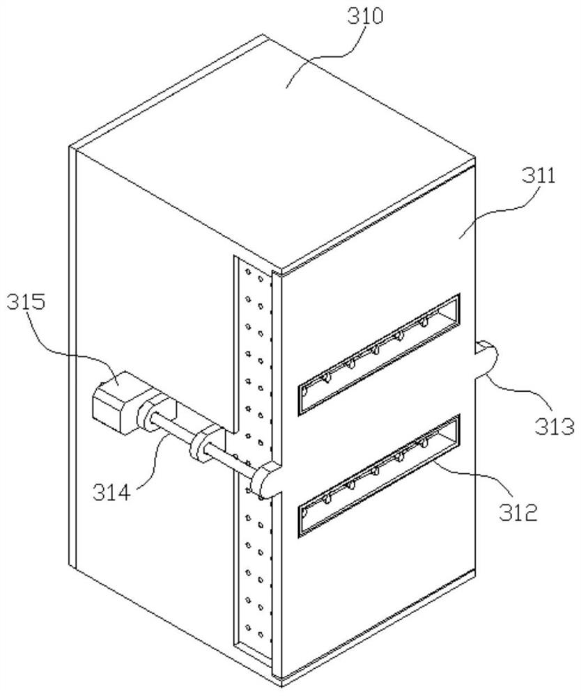
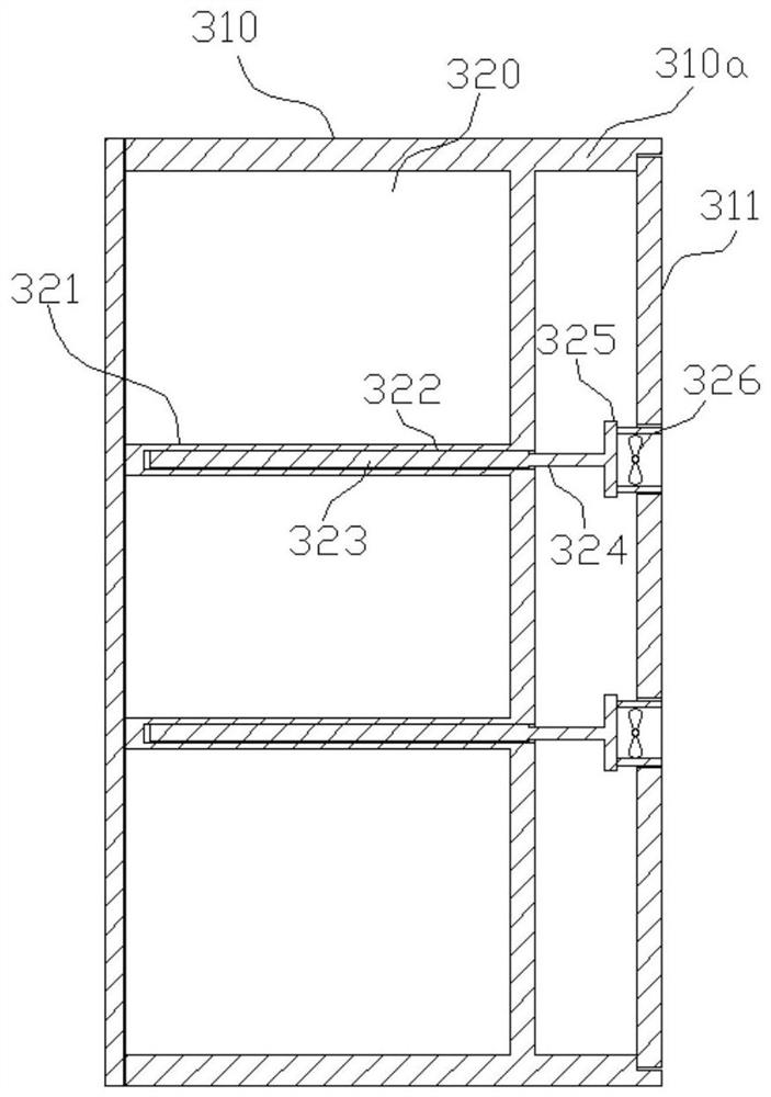
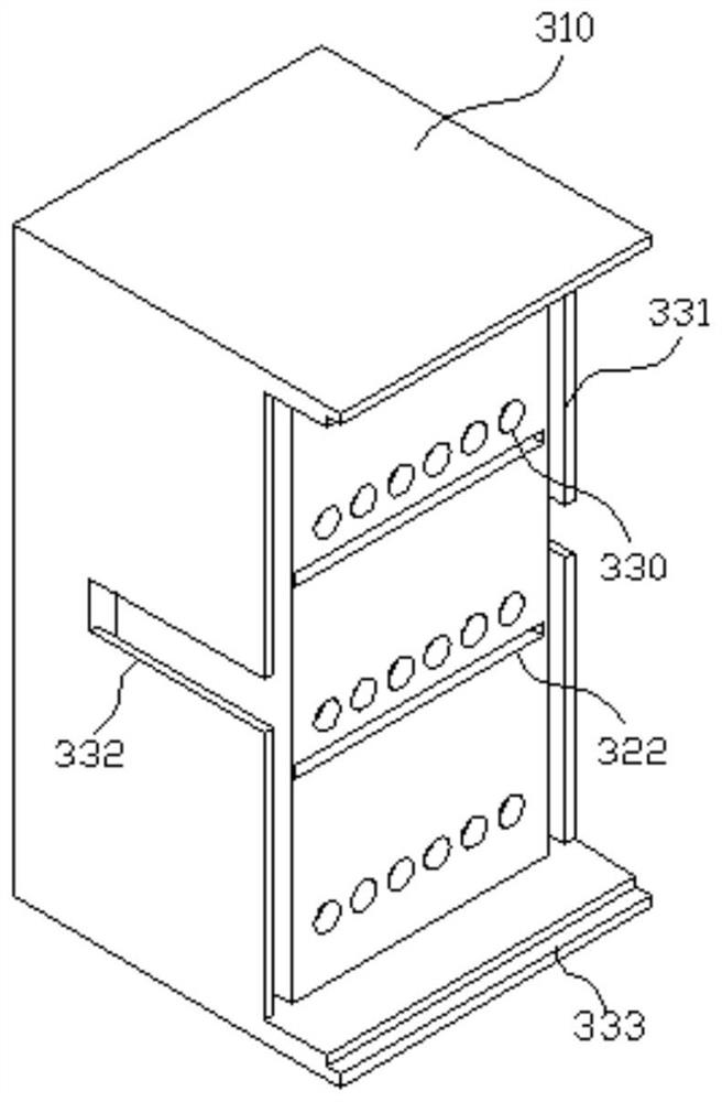
[0042] Such as Figure 1-9 As shown, the present embodiment provides an electrical switch cabinet, which includes a cabinet body 310, the cabinet body 310 is provided with a placement cavity 320 with an opening forward, and the placement cavity 320 is provided with a partition 321; the rear side of the cabinet body 310 And it is located at the upper and lower ends and extends backward to form the installation part 310a, and the installation part 310a is provided with the installation plate 311; The heat conduction plate 323 is connected to a heat sink 325 through a heat conduction pipe 324, and the heat dissipation fan 326 is evenly distributed on the heat sink 325;

[0043]Through the arrangement of the partition plate 321, the mounting plate 311, the heat conduction plate placement cavity 322, the heat conduction plate 323, the heat conduction pipe 324, the heat sink 325 and the cooling fan 326 in this embodiment, the heat conduction plate 323 is installed in the heat conduc...


PUM


Abstract

The invention relates to the technical field of switch cabinets, and discloses an electrical switch cabinet which comprises a shell, a moving cavity with a backward opening is formed in the shell, moving grooves are formed in the left side wall and the right side wall of the moving cavity in the front-back direction, and first ventilating grooves formed in the left-right direction are formed in the front side wall of the moving cavity at intervals. And a slidable moving plate is arranged in each moving cavity, a sliding block extending into the corresponding moving groove is arranged on each moving plate, and second ventilating grooves which are formed in the left-right direction and staggered with the first ventilating grooves are formed in the moving plates at intervals. By means of thestructure, due to the arrangement of the moving cavities, the moving plates, the first ventilation grooves and the second ventilation grooves, the sealing performance and the ventilation performance of the moving cavities are adjusted by adjusting the distance between the moving plates and the front side walls of the moving cavities.

Description

technical field [0001] The invention relates to the technical field of switch cabinets, in particular to an electrical switch cabinet. Background technique [0002] The power switchgear is an important electrical equipment for switching, control and protection in the power system. Switchgear is mainly composed of measuring equipment, circuit breakers, isolating switches, load switches, operating mechanisms and various protection devices, and is widely used in substations, power plants and other places. In the prior art, the door of the switchgear used outside the substation is usually provided with ventilation holes, which are used to circulate the gas in the switchgear in summer high temperature weather, effectively preventing the power equipment in the switchgear from High temperature damage. At this time, when it rains in the outdoor environment, rainwater can enter the switch cabinet through the vent hole, thereby causing damage to the operation of the electrical equipm...

Claims


Application Information

Patent Timeline
Patent Type & Authority Applications(China)
IPC IPC(8): H02B1/30H02B1/28H02B1/56E05C1/10E05B65/52B01D46/00B01D46/10
CPCH02B1/30H02B1/305H02B1/306H02B1/28H02B1/565E05C1/10E05B65/523B01D46/10B01D46/76
Inventor 吴杰
Owner 浙江伟捷电气有限公司
Learn More