A Water Depth Measuring Device Applied to Water Conservancy Surveying

A water depth measurement and water conservancy technology, which is applied in the direction of level indicators of level members, can solve problems affecting water conservancy construction, easy to be destroyed, and lack of flexible operability

Active Publication Date: 2021-04-27
SICHUAN UNIV
View PDF16 Cites 0 Cited by
  • Summary
  • Abstract
  • Description
  • Claims
  • Application Information

AI Technical Summary

Problems solved by technology

[0006] Aiming at the deficiencies of the prior art, the present invention provides a water depth measurement device applied to water conservancy surveys, which overcomes the deficiencies of the prior art, has a reasonable design and a compact structure, and aims to solve the problem of installing the existing water depth measurement device on a survey ship. , lack of flexible operability, it is easy to be damaged, and manual setting-out or operation is used, which increases the cost of labor labor; at the same time, the result of single-set-out measurement is inaccurate, which affects the problem of water conservancy construction

Method used


Image

  • A Water Depth Measuring Device Applied to Water Conservancy Surveying
  • A Water Depth Measuring Device Applied to Water Conservancy Surveying
  • A Water Depth Measuring Device Applied to Water Conservancy Surveying

Examples


Embodiment 1

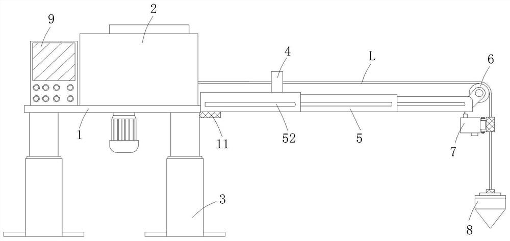
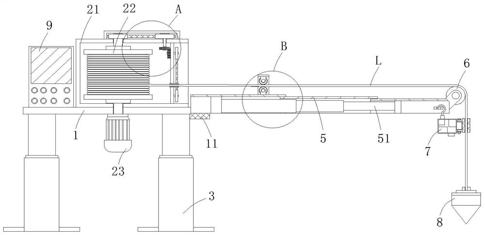
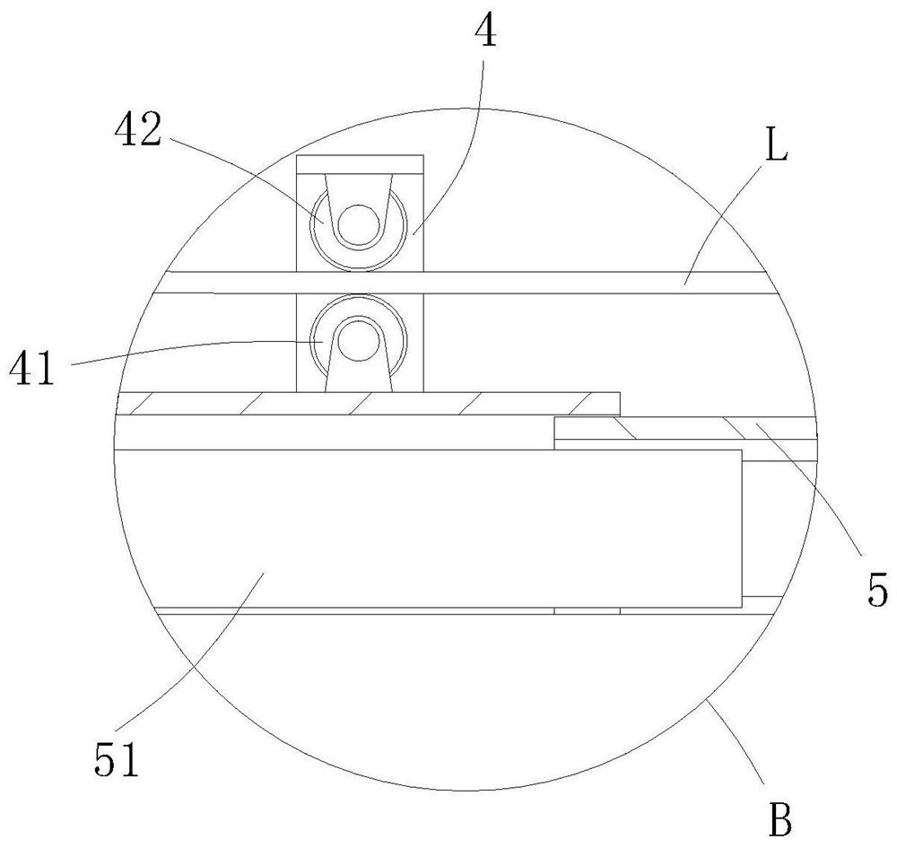
[0036]A water depth measuring device applied to water conservancy surveying, comprising a horizontally arranged working disk 1, the working disk 1 is installed on the upper end of a hydraulic lifting support 3, and the hydraulic lifting support 3 is detachably fixed on the measuring hull by bolts, and the working The upper end of the disk 1 is equipped with a weight wire retractable mechanism 2, and the weight wire L extended from the weight wire retractable mechanism 2 bypasses the steering wheel 6 and is equipped with a measuring weight 8, and the steering wheel 6 is installed by rotating the bracket On the free end of the telescopic bracket 5, and the telescopic bracket 5 is fixedly installed on the side wall of the working disk 1, the telescopic bracket 5 is composed of a plurality of combined frames whose lower ends are not closed in sequence, and the telescopic bracket The inside of 5 is provided with telescopic cylinder 51 for controlling telescopic bracket 5 free ends t...

Embodiment 2

[0048] The difference between this embodiment and embodiment 1 is that, as Figure 5 As shown, the upper end of the measuring weight 8 is equipped with a pressure sensor 10, and the pressure sensor 10 is sleeved on the weight line L, and the pressure sensor 10 can slide the sleeve when the acceleration sensor 73 falls to the measuring weight 8. 71 collides with the pressure sensor 10, and then transmits the complete trajectory and water depth data, which can also effectively ensure that this measurement has completely reached the water bottom at the position of the measuring weight 8.

[0049] Refer to Example 1 for other undescribed structures.


PUM


Abstract

The invention relates to the technical field of water conservancy measurement equipment, and provides a water depth measurement device applied to water conservancy measurement, aiming at solving the problem that the existing water depth measurement device is installed on a survey ship, which is easily damaged, and manual setting or operation is used. Increased the cost of manual labor; at the same time, the problem of inaccurate results of single setting-out measurement, including the horizontal setting of the work plate, the work plate is installed on the upper end of the hydraulic lifting support, and the upper end of the work plate is equipped with a weight line retractable mechanism, and the weight line extended from the weight line retracting mechanism bypasses the steering wheel and is equipped with a measuring weight. The lower side of the free end of the telescopic bracket is equipped with a track measuring mechanism, and the upper end of the telescopic bracket is equipped with a control wheel. frame, and the inside of the wire control wheel frame is equipped with a wire control wheel and a roller meter counter. The invention is especially suitable for water depth measurement in water conservancy construction, and has high social use value and application prospect.

Description

technical field [0001] The invention relates to the technical field of water conservancy measurement equipment, in particular to a water depth measurement device applied to water conservancy measurement. Background technique [0002] The term water conservancy was first seen in the chapter "Filial Piety and Caution for People" in "Lu Shi Chunqiu" published at the end of the Warring States period, but the "water conservancy" it talks about refers to the benefits of fishing. Due to the continuous development of modern society, economy and technology, the connotation of water conservancy is also constantly enriched and expanded. In 1933, the resolution of the third annual meeting of the Chinese Hydraulic Engineering Society clearly pointed out: "The scope of water conservancy should include flood control, drainage, irrigation, water power, waterways, etc. , water supply, sewage drains, and port engineering projects." The term water conservancy can be summarized as: human socie...

Claims


Application Information

Patent Timeline
Patent Type & Authority Patents(China)
IPC IPC(8): G01F23/04
CPCG01F23/04
Inventor 杨正丽项霞鲁恒宋凯卢修元蔡诗响夏鹏飞
Owner SICHUAN UNIV
Why Eureka
Try Eureka