
Auxiliary explosion-proof system for coal mine air shaft

A technology of explosion-proof system and air well, which is applied in mine/tunnel ventilation, mining equipment, mining equipment, etc., and can solve the problems of high technical cost and difficulty

Active Publication Date: 2020-10-23
HENAN POLYTECHNIC UNIV
View PDF6 Cites 1 Cited by
  • Summary
  • Abstract
  • Description
  • Claims
  • Application Information

AI Technical Summary

Problems solved by technology

[0004] Aiming at the defects and hidden dangers of the current explosion-proof doors for air shafts, and centering on the technical goal of quick reset of the explosion-proof doors after disasters, many new types of explosion-proof doors for air shafts have been proposed in China, and the anti-blast performance and safety of the explosion-proof doors are generally enhanced from the aspects of guidance, buffering, and limit. Reset reliability; however, the explosion-proof door of the wind shaft is a large structure, which will obtain huge impact energy in the explosion, and it is extremely difficult to apply technical measures such as guiding, buffering, and limiting, and the corresponding technical costs are also very high

Method used


Image

  • Auxiliary explosion-proof system for coal mine air shaft
  • Auxiliary explosion-proof system for coal mine air shaft
  • Auxiliary explosion-proof system for coal mine air shaft

Examples


Embodiment Construction

[0030] The present invention will be further described below in conjunction with the accompanying drawings and specific embodiments. The schematic embodiments and descriptions of the present invention are used to explain the present invention, but are not intended to limit the present invention.

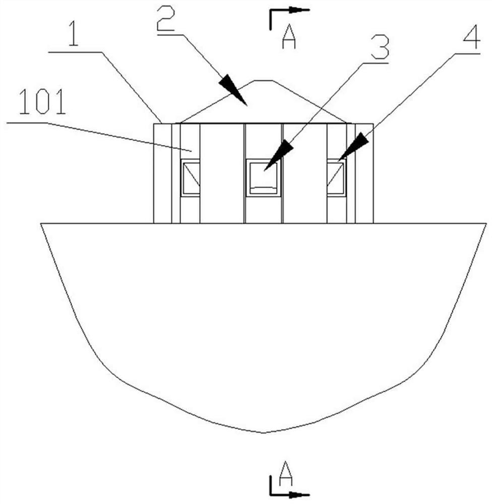
[0031] Such as Figure 1-8 The coal mine air shaft auxiliary explosion-proof system shown is arranged at the wellhead of the air shaft. A wellhead base 1 is arranged around the wellhead of the air shaft. The wellhead base 1 is cylindrical and made of reinforced concrete. The wellhead A main explosion-proof door 2 is installed on the upper end of the base body 1. The wellhead base body 1 protrudes upwards from the ground and extends a section of well wall 101. A number of auxiliary explosion-venting passages 3 are arranged at intervals on the well wall 101 in a circular array. The explosion passage 3 runs through the well wall 101, and the surface of the well wall 101 at the external ...


PUM


Abstract

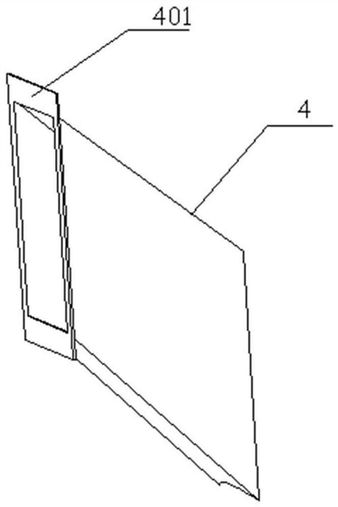
The invention discloses an auxiliary explosion-proof system for a coal mine air shaft. The auxiliary explosion-proof system is arranged at a shaft opening of an air shaft, and a shaft opening basal body is arranged at the periphery of the shaft opening of the air shaft and is manufactured through pouring with reinforced concrete; a main explosion-proof door is mounted at the upper end of the shaftopening basal body, the shaft opening basal body upwards protrudes the ground and extends from a segment of a shaft wall, and a plurality of auxiliary explosion venting passages are arranged on the shaft wall in a circumferential array manner in a spacing manner, and penetrate through the shaft wall; a metal explosion venting pipeline is inlaid in each auxiliary explosion venting passage, and themetal explosion venting pipelines and the shaft opening basal body are fixed together through cement pouring; a flange is welded to the outside edge of each metal explosion venting pipeline, and an auxiliary explosion-proof door is mounted on each flange; the auxiliary explosion venting passages can realize pressure relief in advance and process pressure relief of explosion shock waves, and substantially reduce the shock and damage effects of the explosion shock waves on the main explosion-proof door at the shaft opening; and door panels and support frameworks of the auxiliary explosion-proofdoor are designed in a separated manner, so that the auxiliary explosion-proof doors are good in explosion venting effects, have adaptability to explosion shock and are difficult to damage.

Description

technical field [0001] The invention relates to the technical field of coal mine air shaft safety, in particular to an auxiliary explosion-proof system and an explosion relief method for a coal mine air shaft, which are used to reduce the blast wave impact suffered by a main explosion-proof door of a coal mine air shaft. Background technique [0002] The coal mine air shaft explosion-proof door is an important explosion venting facility to protect the mine main ventilator. Its function is to quickly release the explosion impact airflow in the air shaft in the event of an explosion, thereby protecting the coal mine main ventilator from destructive impact. [0003] At present, a bell-shaped explosion-proof door is generally used in vertical wind shafts of coal mines in my country, which is composed of a door body, a sealed oil tank, a pulley frame, a counterweight, and a traction wire rope. This type of explosion-proof door lacks a reliable guiding mechanism, and has no buffer...

Claims


Application Information

Patent Timeline
IPC IPC(8): E21F1/10E21F17/103E21F17/00E06B5/12E06B3/70E05F5/06
CPCE21F1/10E21F17/103E21F17/00E06B5/12E06B3/70E05F5/06
Inventor 宋维宾孙玉宁王明中王永龙王振锋
Owner HENAN POLYTECHNIC UNIV
Learn More