
Multifunctional balcony protection window

A protective window and multi-functional technology, applied in the direction of window/door frame, shutter/movable grille, washing device, etc., can solve problems such as difficult installation, limited use environment, hidden safety hazards of circuit devices, etc.

Inactive Publication Date: 2020-10-23
马悦
View PDF1 Cites 2 Cited by
  • Summary
  • Abstract
  • Description
  • Claims
  • Application Information

AI Technical Summary

Problems solved by technology

[0002] Protective windows are common home decoration products, and almost every household needs to install protective windows. The existing balcony protective windows achieve the protective effect by installing external iron cage railings, openable railings or up and down telescopic railings; Cage-type protective windows not only visually affect the overall effect of urban planning, but also hinder the escape of indoor personnel in the event of a fire; the protective windows with openable railings and the protective windows with retractable railings are more beautiful in style, but the structure is complex and difficult to install. Large, especially inconvenient for high-rise installation;
[0003] For example, the Chinese utility model patent No. CN01268956 discloses a multifunctional window guardrail, which includes a decorative edge, a window frame, a window sash, an automatic alarm circuit a, a high-voltage generating circuit b, an automatic control circuit, a control box, etc., which can realize The function of anti-theft and drying clothes, but the structure is complicated, and the circuit device is exposed to the outside of the window for a long time, which has great safety hazards, and the use environment is limited, and the equipment cost is too high;

Method used


Image

  • Multifunctional balcony protection window
  • Multifunctional balcony protection window
  • Multifunctional balcony protection window

Examples


Embodiment Construction

[0024] The technical solutions in the embodiments of the present invention are clearly and completely described below in conjunction with the drawings in the embodiments of the present invention. Apparently, the described embodiments are only some of the embodiments of the present invention, but not all of them. Based on the embodiments of the present invention, all other embodiments obtained by persons of ordinary skill in the art without making creative efforts belong to the protection scope of the present invention.

[0025] In the description of the present invention, it should be noted that the orientation or positional relationship indicated by the terms "up", "down", "front", "rear", "left", "right" etc. are based on the Orientation or positional relationship, or the orientation or positional relationship that the inventive product is usually placed in use, is only for the convenience of describing the present invention and simplifying the description, rather than indic...


PUM


Abstract

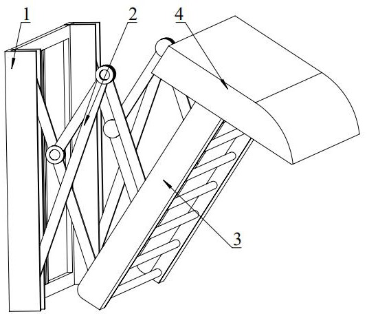
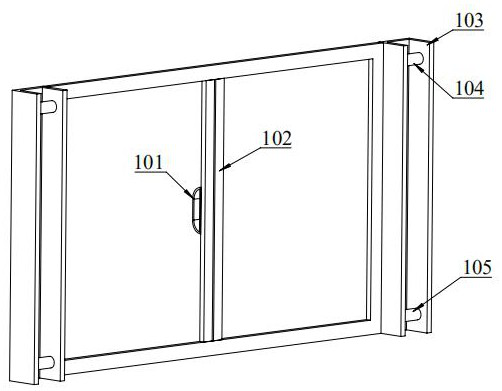
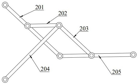
The invention relates to a multifunctional balcony protection window. The multifunctional balcony protection window comprises a window body, protection barriers, a protection cover and connecting rodmechanisms; the window body is fixed to a balcony, one ends of the connecting rod mechanisms are rotationally connected with the window body, and the other ends of the connecting rod mechanisms are rotationally connected with the protection barriers; and the protection cover is fixedly installed at the tops of the protection barriers. According to the multifunctional balcony protection window, theprotection barriers have two states of longitudinal placement and transverse placement, the protection barriers are transversely placed to serve as clothes airing supports, and the protection barriers are longitudinally placed to cover the window body to serve as an anti-theft window; the connecting rod mechanisms are fixedly connected with multiple points of the protection barriers, so that thebearing capacity of the protection barriers is improved; and the protection barriers are zinc steel protection barriers, so that the protection barriers made of the material is high in corrosion resistance and can resist exposure to the sun and invasion of wind, rain and snow at any time.

Description

technical field [0001] The invention relates to the technical field of building protection, in particular to the field of a multifunctional balcony protective window. Background technique [0002] Protective windows are common home decoration products, and almost every household needs to install protective windows. The existing balcony protective windows achieve the protective effect by installing external iron cage railings, openable railings or up and down telescopic railings; Cage-type protective windows not only visually affect the overall effect of urban planning, but also hinder the escape of indoor personnel in the event of a fire; the protective windows with openable railings and the protective windows with retractable railings are more beautiful in style, but the structure is complex and difficult to install. Large, especially inconvenient for high-rise installation; [0003] For example, the Chinese utility model patent No. CN01268956 discloses a multifunctional w...

Claims


Application Information

Patent Timeline
IPC IPC(8): E06B9/04D06F57/12D06F57/10E06B7/26E06B1/36
CPCD06F57/10D06F57/12E06B1/36E06B7/26E06B9/04
Inventor 马悦
Owner 马悦
Learn More