
Typical formwork for concrete drainage pipe junction plaster band construction, and construction method

A technology for shaping formwork and concrete, applied in formwork/formwork/work frame, sewer pipe system, non-removable pipe connection, etc., which can solve the problems of slurry leakage, increased engineering cost and low construction efficiency.

Pending Publication Date: 2020-10-23
CCCC THIRD HARBOR ENG
View PDF0 Cites 2 Cited by
  • Summary
  • Abstract
  • Description
  • Claims
  • Application Information

AI Technical Summary

Problems solved by technology

[0003] At present, there are still problems in the wiping tape construction, such as difficult control of the thickness of the wiping tape, low construction efficiency, and serious grout leakage, resulting in a large loss of mortar, which seriously affects the construction progress and quality, and increases the project cost.

Method used


Image

  • Typical formwork for concrete drainage pipe junction plaster band construction, and construction method
  • Typical formwork for concrete drainage pipe junction plaster band construction, and construction method
  • Typical formwork for concrete drainage pipe junction plaster band construction, and construction method

Examples


Embodiment Construction

[0014] The present invention will be further described below in conjunction with accompanying drawing.

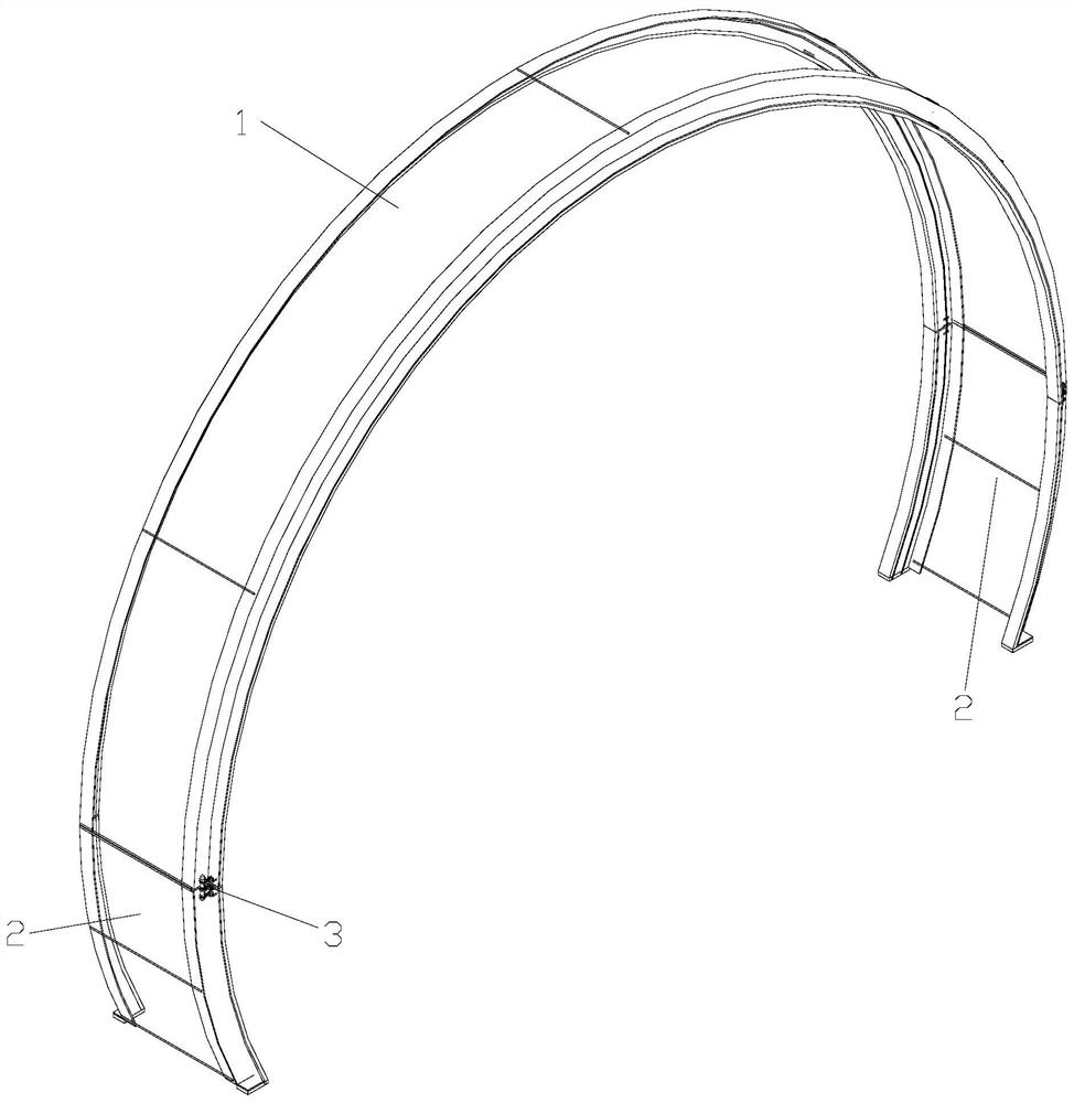
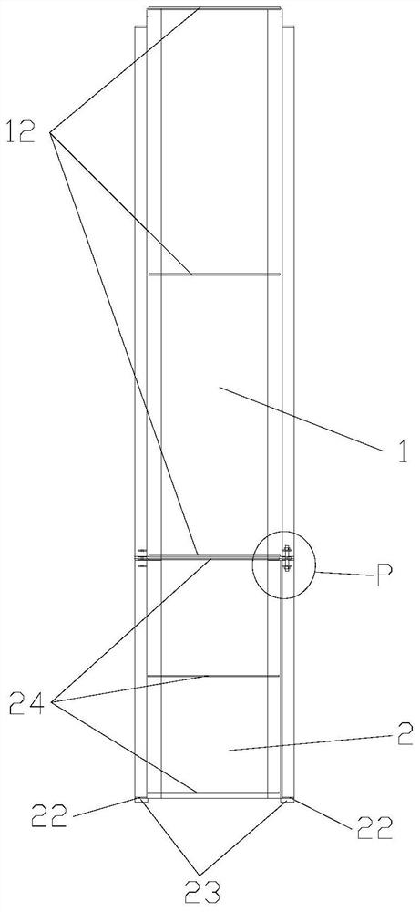
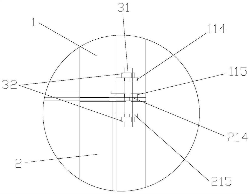
[0015] see Figure 1 to Figure 7 , the concrete drainpipe interface of the present invention is equipped with a sizing formwork for wiping tape construction, comprising a top form 1 and two side forms 2 .

[0016] The top mold 1 includes two top side plates 11, five top connecting rods 12 and two top rubber stopper strips 13; wherein,

[0017] The two top side panels 11 are arranged symmetrically on both sides of the interface of the concrete drain pipe, and the distance between the two top side panels 11 is equal to the width of the wiping belt, 15cm-20cm; the cross section of each top side panel 11 is Z-shaped and includes a semicircular arc Shaped top inner ring plate 111 and top outer ring plate 112 and the top radial plate 113 connected between the inner end of the top inner ring plate 11 and the outer end of the top outer ring plate 112; the inner diameter of the top...


PUM

PropertyMeasurementUnit
Thicknessaaaaaaaaaa

Abstract

The invention discloses a typical formwork for concrete drainage pipe junction plaster band construction. The typical formwork comprises a top formwork and two side formworks; the top formwork comprises two top side plates, five top connecting rods and two top rubber pulp-stop strips; the distance between the two top side plates is equal to the width of a plaster band, and the cross section of each top side plate is in a Z shape; the two side formworks are the same in structure, and each side formwork comprises two lateral side plates, two baffles, two rubber pulp-stop mats, three lateral connecting rods and two lateral rubber pulp-stop strips, wherein the two lateral side plates are symmetrically arranged, and the distance between the two lateral side plates is equal to the width of the plaster band, and the cross section of each lateral side plate is in a Z shape; and the upper ends of the two side formworks are connected with the two ends of the top formwork in a one-to-one correspondence mode through two sets of connecting pieces correspondingly, and the lower ends of the two side formworks are arranged on the top face of a concrete foundation of a drainage pipe. The inventionfurther discloses a construction method of the concrete drainage pipe. The width and thickness of the plaster band can be controlled, plug leakage of the plaster band can be prevented, and the water-stop effect of the plaster band is effectively ensured.

Description

technical field [0001] The invention relates to a stereotyped formwork and a construction method for tape construction of concrete drainage pipe joints. Background technique [0002] During the installation and construction of concrete drainage pipes, it is necessary to butt the pipes, and then seal them with cement mortar and steel mesh tape. If there is leakage in the drainage pipes, it may cause sand and soil loss, resulting in loose or even hollow foundation soil, which will cause damage to the upper structure. Therefore, it is particularly important to prevent leakage of drainage pipes. [0003] At present, there are still problems in the wiping tape construction, such as difficult control of the thickness of the wiping tape, low construction efficiency, and serious grout leakage, resulting in a large loss of mortar, which seriously affects the construction progress and quality, and increases the project cost. Contents of the invention [0004] The purpose of the pre...

Claims


Application Information

Patent Timeline
IPC IPC(8): E03F3/06E04G13/00F16L1/06F16L1/024F16L13/12
CPCE03F3/06E04G13/00F16L1/024F16L1/06F16L13/124
Inventor 嵇静戴志培韦奋祥徐伟何风黔唐庆龙张继彪
Owner CCCC THIRD HARBOR ENG
Learn More